はじめに
前回の記事では,一方向にのみ剛性が小さい構造としてスライダー構造の挙動を簡易的に計算しました。また,スライダー構造では,変形を誘導したい梁板厚方向の剛性が単純な片持ち梁と比べて高くなることを述べました。
本記事では,より低剛性化する方法とその際に生じる課題について述べます。
X方向を低剛性化させるには
X方向に変形誘導させたい場合は,コンプライアンス行列のX方向に関する\(S_{11}\)成分を他とと比較して大きくすればよいです。
\(\begin{bmatrix} d_x \\ d_y \\ \theta_z \\\end{bmatrix}
= \begin{bmatrix}
S_{11} & S_{12} & S_{16} \\ & S_{22} & S_{26} \\ \text{sym.} & & S_{66} \end{bmatrix}
\begin{bmatrix} F_x \\ F_y \\ M_z \\\end{bmatrix}\)
前回の記事で,直列につないだ梁の挙動はコンプライアンス行列の足し合わせで求められ,梁を直列につなぐことで変形を大きくできることを述べました。
コンプライアンス行列成分値の比(\(S_{11}/S_{22}\)や\(S_{11}/S_{66}\)など)を大きくするには,より比が大きい構造を結合しなくてはりません。Y方向荷重とZ軸回転モーメントに対して梁の軸力が作用するスライダー構造以上にこれらの比が大きな構造はなく,\(S_{11}\)をより大きくする場合は,その他の変形が大きくなる(\(S_{11}/S_{22}\)や\(S_{11}/S_{66}\)が小さくなる)こと許容する必要があります。
逆に,剛性異方性がより顕著な構造は梁の配置を変えるだけでは実現できず,梁厚を小さくするか梁長を伸ばすしかありません。ただし,座屈強度や製造制約を考えると薄くするには限りがあります。(構造作製後に荷重をかけて変形させることを許容する場合は,QZS構造を用いることで解決できる場合もあります。)
スライダー構造を直列に接続する
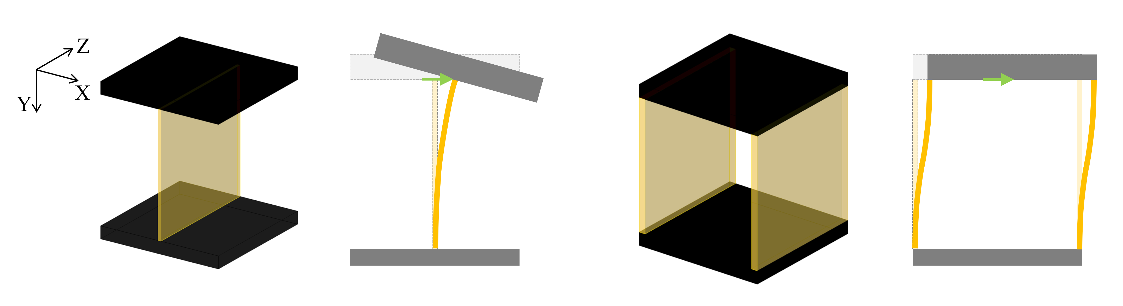
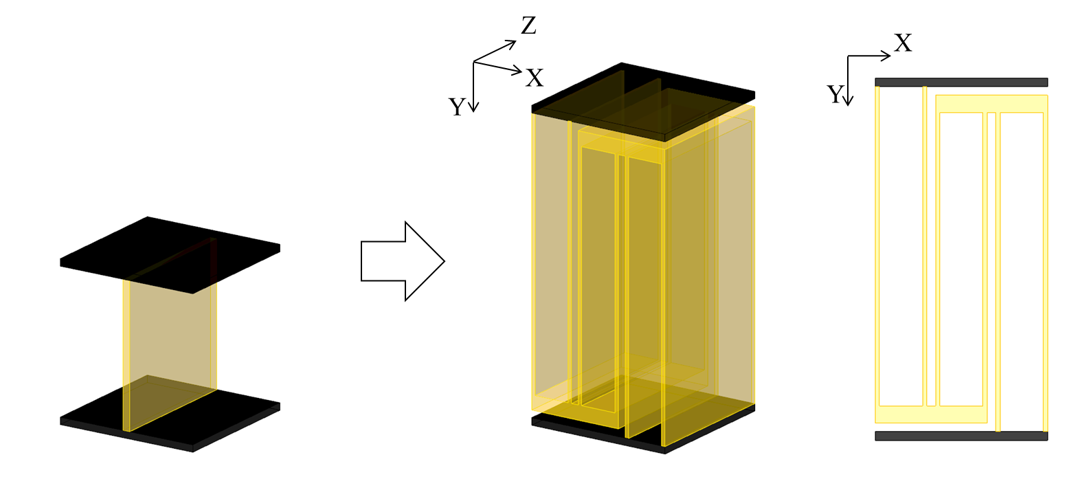
Y方向や回転に対する剛性を大きく損なわずにX方向の剛性を下げるため,次のように形状を変更します。
- 設計領域を拡大し,Y方向寸法を20mmから40mmに変更する
- 梁厚を1 mmから0.5 mmに変更する
- スライダー構造を直列に接続する
方向荷重1 Nをかけた際の挙動は次のようになります。細い 点線は片持ち梁を,実線は上図の直列構造を示します。
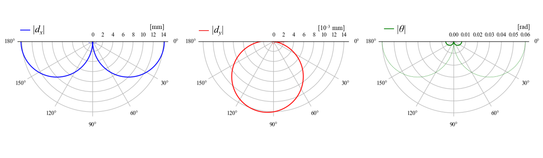
片持ち梁に比べて,X方向の変形を大きく回転角を小さく出来ていることが分かります。Y方向の変位は大きくなっていますが,X方向の変位と比較すると無視できる大きさです。
このように,Y方向変位や回転をわずかに許容すれば,構造を直列に接続することでX方向に低剛性化した構造が得られます。
ねじれ変形が大きくなる
これでめでたしめでたし,とはならないのが面白いところです。低剛性化したことにより,これまで考慮していなかった面外方向の剛性が問題となってくることがあります。
3次元の変形挙動
面外方向の変形を考慮するには,3次元での挙動を考える必要があります。空間機構の考え方を用いると,概ね2次元の場合と同じように簡易的に計算することができます。
面外変形も考慮した場合,一様梁のコンプライアンス行列\([S]\)は次式のようになります。
\(\boldsymbol{T} = [S]\boldsymbol{W}\\
\begin{bmatrix} d_x \\ d_y \\ d_z \\ \theta_x \\ \theta_y \\ \theta_z \\\end{bmatrix}
= \begin{bmatrix}
\frac{l^3}{3EI_x} & 0 & 0 & 0 & 0 & \frac{l^2}{2EI_x}\\
0 & \frac{l}{Ebh} & 0 & 0 & 0 & 0\\
0 & 0 & \frac{l^3}{3EI_z} & -\frac{l^2}{2EI_z} & 0 & 0 \\
0 & 0 & -\frac{l^2}{2EI_z} & \frac{l}{EI_z} & 0 & 0 \\
0 & 0 & 0 & 0 & \frac{l}{GJ} & 0 \\
\frac{l^2}{2EI_x} & 0 & 0 & 0 & 0 & \frac{l}{EI_x} \end{bmatrix}
\begin{bmatrix} F_x \\ F_y \\ F_z \\ M_x \\ M_y \\ M_z \\\end{bmatrix}\)
ここで,Jは梁のねじり定数であり,今回は次式を用いました。
\(J = \frac{bh^3}{3} \left(1-\frac{192h}{\pi^5b} \sum_{n=1}^{\infty} {1 \over 2n-1}\tanh{(2n-1)\pi b\over 2h}\right)\)
\(\boldsymbol{W'}\)から\(\boldsymbol{W}\)への座標変換行列を\([N]\)とすると,
\(\boldsymbol{W} = [N] \boldsymbol{W'}\\
\begin{bmatrix} F_x \\ F_y \\ F_z \\ M_x \\ M_y \\ M_z \\\end{bmatrix} = \begin{bmatrix}
\boldsymbol{n_1} &
\boldsymbol{n_2} &
\boldsymbol{n_3} &
\boldsymbol{0} &
\boldsymbol{0} &
\boldsymbol{0} \\
\boldsymbol{L} \times \boldsymbol{n_1} &
\boldsymbol{L} \times \boldsymbol{n_2} &
\boldsymbol{L} \times \boldsymbol{n_3} &
\boldsymbol{n_1} &
\boldsymbol{n_2} &
\boldsymbol{n_3}
\end{bmatrix}
\begin{bmatrix}
F_x' \\ F_y' \\ F_z' \\ M_x' \\ M_y' \\ M_z' \\\end{bmatrix}\)
梁が移動した場合の剛性行列は次のように表されます。
\([Q] = [N][Q'][N]^\boldsymbol{T}\)
ここで,変換行列\([N]\)内の\(\boldsymbol{n_1}\),\(\boldsymbol{n_2}\),\(\boldsymbol{n_3}\)はX'Y'Z'の各軸方向単位ベクトルであり,\(\boldsymbol{L}\)は梁先端の位置ベクトルを表します。
梁を直列や並列に接続する場合の挙動も,2次元と同様にコンプライアンス行列や剛性行列の足し合わせで求めることができます。
固有振動モード
構造の剛性異方性は固有振動モードを見ることでも理解できます(適用先によってはこちらの方が実問題として考えやすい場合もあります)。固有振動数の低いモードは剛性が低いことを表します。
固有振動値および振動モードは,慣性を考慮した運動方程式を用いて求めることができます。
\([M]\frac{d^2 \boldsymbol{T}}{dt^2} + [Q]\boldsymbol{T} = \boldsymbol{W}\)
ここで,\([M]\)は質量と慣性テンソルにより構築された行列(\(diag(m,m,m,I_x,I_y,I_z)\))を座標変換したものを用います。荷重が0のとき,固有振動数\(\omega_n\)に対して次式が成り立ちます。
\([M]^{-1}[Q]\boldsymbol{T} = \omega_n^2\boldsymbol{T}\)
このため,\([M]^{-1}[Q]\)の固有値および固有ベクトルを計算することで,6自由度の固有振動数と固有振動モードを求めることができます。
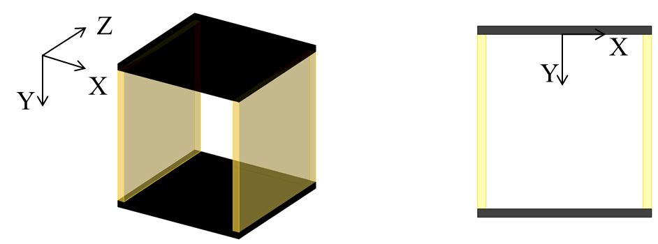
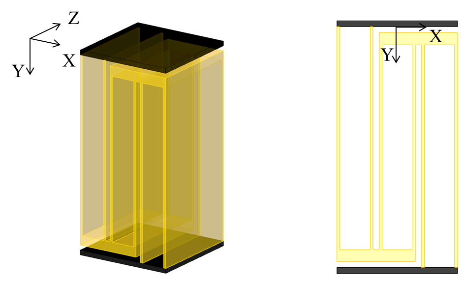
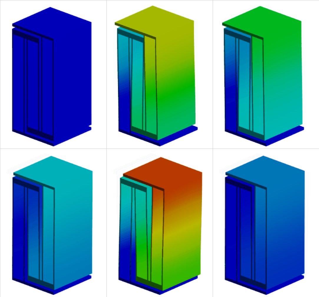
下の表に,前回の記事で扱った梁厚1 mmのスライダー構造単体と上記の直列構造について,固有振動数および固有ベクトルを比較します。構造上部は板厚1 mmの鋼(密度 7850 kg/m^3)としました。各固有ベクトルはノルムが1となるように正規化しており,成分の絶対値に意味はありません。
スライダー構造
| 1次 | 2次 | 3次 | 4次 | 5次 | 6次 | |
|---|---|---|---|---|---|---|
| 固有振動数[Hz] | 284 | 2073 | 3481 | 4922 | 5680 | 7772 |
| dx [m] | 0.97 | 0 | 0 | 0 | 0 | 0 |
| dy [m] | 0 | 0 | 0 | 0 | 1 | 0 |
| dz [m] | 0 | -0.01 | 0 | 0 | 0 | 0.01 |
| θx [rad] | 0 | 1.00 | 0 | 0 | 0 | 1.00 |
| θy [rad] | 0 | 0 | 1 | 0 | 0 | 0 |
| θz [rad] | 0.24 | 0 | 0 | 1 | 0 | 0 |
直列構造
| 1次 | 2次 | 3次 | 4次 | 5次 | 6次 | |
|---|---|---|---|---|---|---|
| 固有振動数[Hz] | 23 | 168 | 309 | 426 | 758 | 1154 |
| dx [m] | 0.90 | 0 | 0 | 0 | 0 | 0 |
| dy [m] | 0 | 0 | 0 | 0 | 1 | 0 |
| dz [m] | 0 | 0 | -0.04 | 0 | 0 | 0.00 |
| θx [rad] | 0 | 0 | 1.00 | 0 | 0 | 1.00 |
| θy [rad] | 0 | 1 | 0 | 0 | 0 | 0 |
| θz [rad] | 0.43 | 0 | 0 | 1 | 0 | 0 |
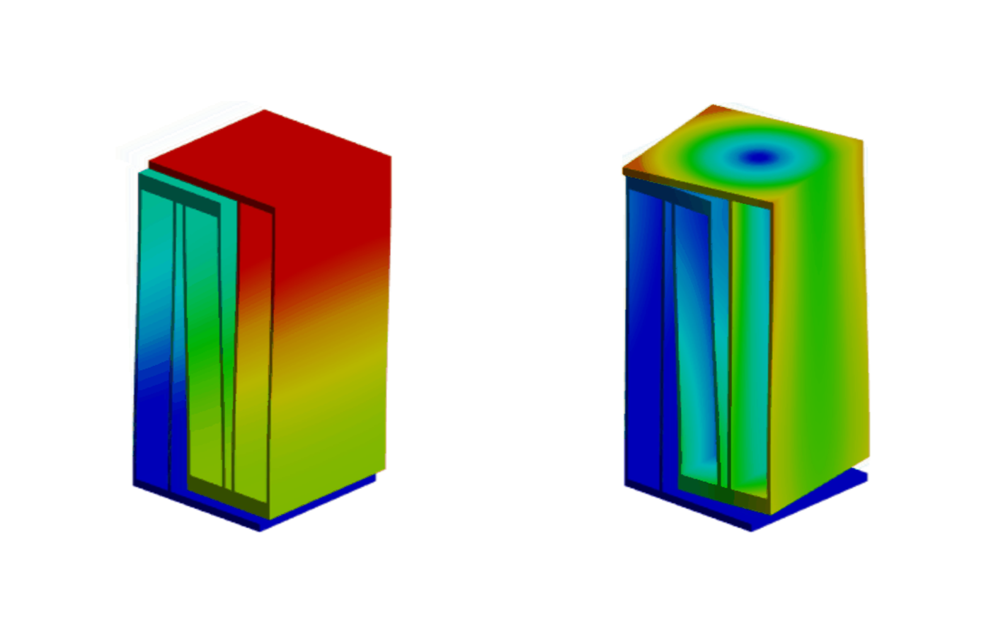
固有振動数を比較すると,直列構造が各モードに対して低剛性化されていることが分かります。どちらの構造においても1次モードにZ軸回転が現れていますが,回転中心を計算するとy = 4.0 m, y=2.1mとなり全体寸法からするとかなり遠くにあるため,ほぼX方向の並進運動であることが分かります。Y軸まわりの回転に近い変形モードは,単体構造では3次モードだったのに対し,直列構造では2次モードとなっています。
このように,X方向に対して低剛性化する際にはXY面外に関する剛性も小さくなり,特に長手方向軸周りの回転に対する剛性が小さくなります。
スライダー構造のねじれ特性
ねじりに対する剛性が小さくなったのは,スライダ構造の特性によるものです。単純な片持ち梁とスライダ構造において,寸法を変化した際のねじれ特性を比較します。厚さや長さを変更したとき,\(\theta_y\)に関するコンプライアンス行列対角成分\(S_{55}\)は次のように変化します。
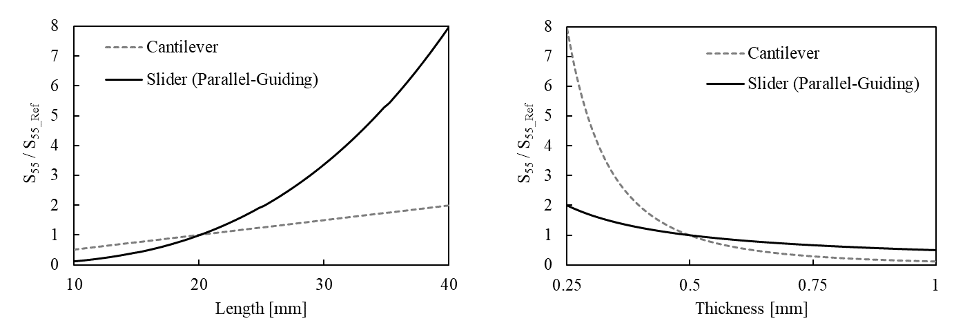
どちらの構造も幅20 mm,厚さ0.5 mm,長さ20 mmのときを基準として表示しています。スライダ構造の梁は±10 mmの位置で固定しました。このように梁長を大きく梁厚を小さくするとき,点線で示す片持ち梁に比べて,実線で示すスライダー構造は\(S_{55}\)の変化が大きくなっています。すなわち,X方向の剛性を小さくように調整する場合,スライダー構造の方がねじれ変形が大きくなりやすいことが分かります。
また,今回の直列構造では,梁間が小さくなったことも大きく影響しています。下図に,梁間距離に対する\(S_{55}\)の変化を示します。

梁間が小さくなると片持ち梁構造に近づき,よりねじれやすくなります。梁間距離を大きく保つには押出状制約も無くす必要があります。
ねじれに対する高剛性化
スライダー構造を直列に接続した構造は,ねじれに対する剛性が小さくなってしまいました。X方向変位に対する剛性を大幅に高くせずに,ねじれを高剛性化できないかを考えてみます。
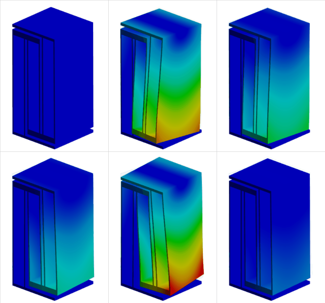
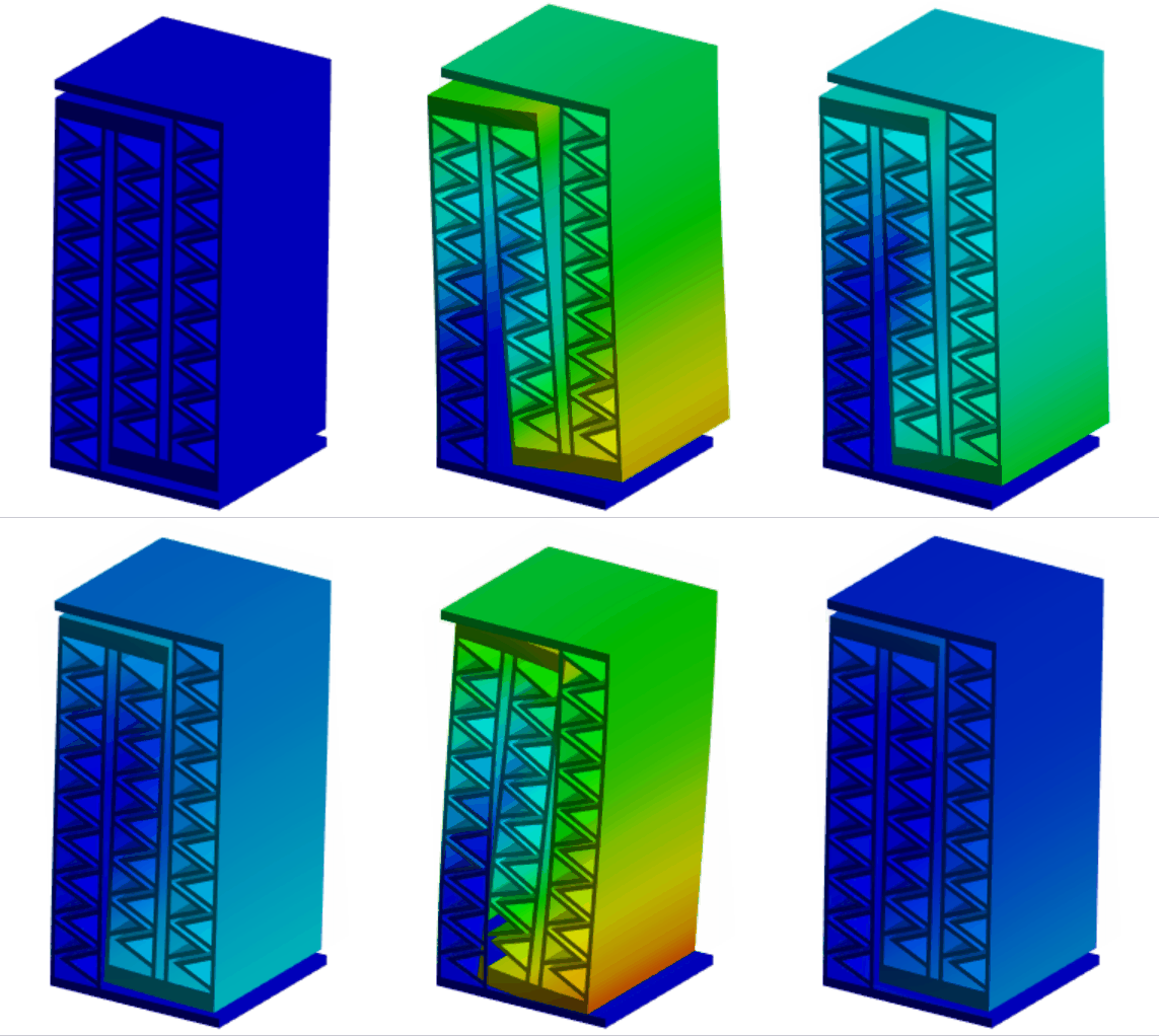
図のように,各梁に曲げ変形のみが生じやすい構造を適用したものを試します。
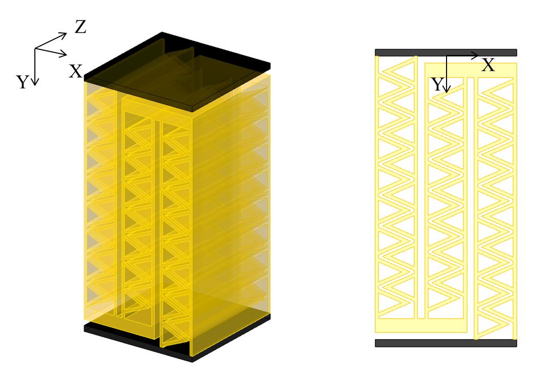
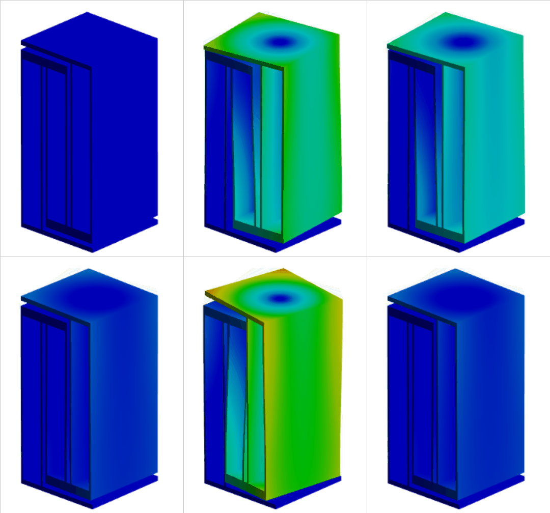
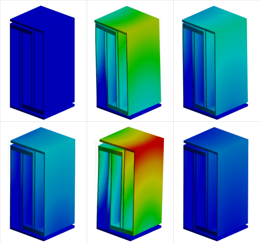
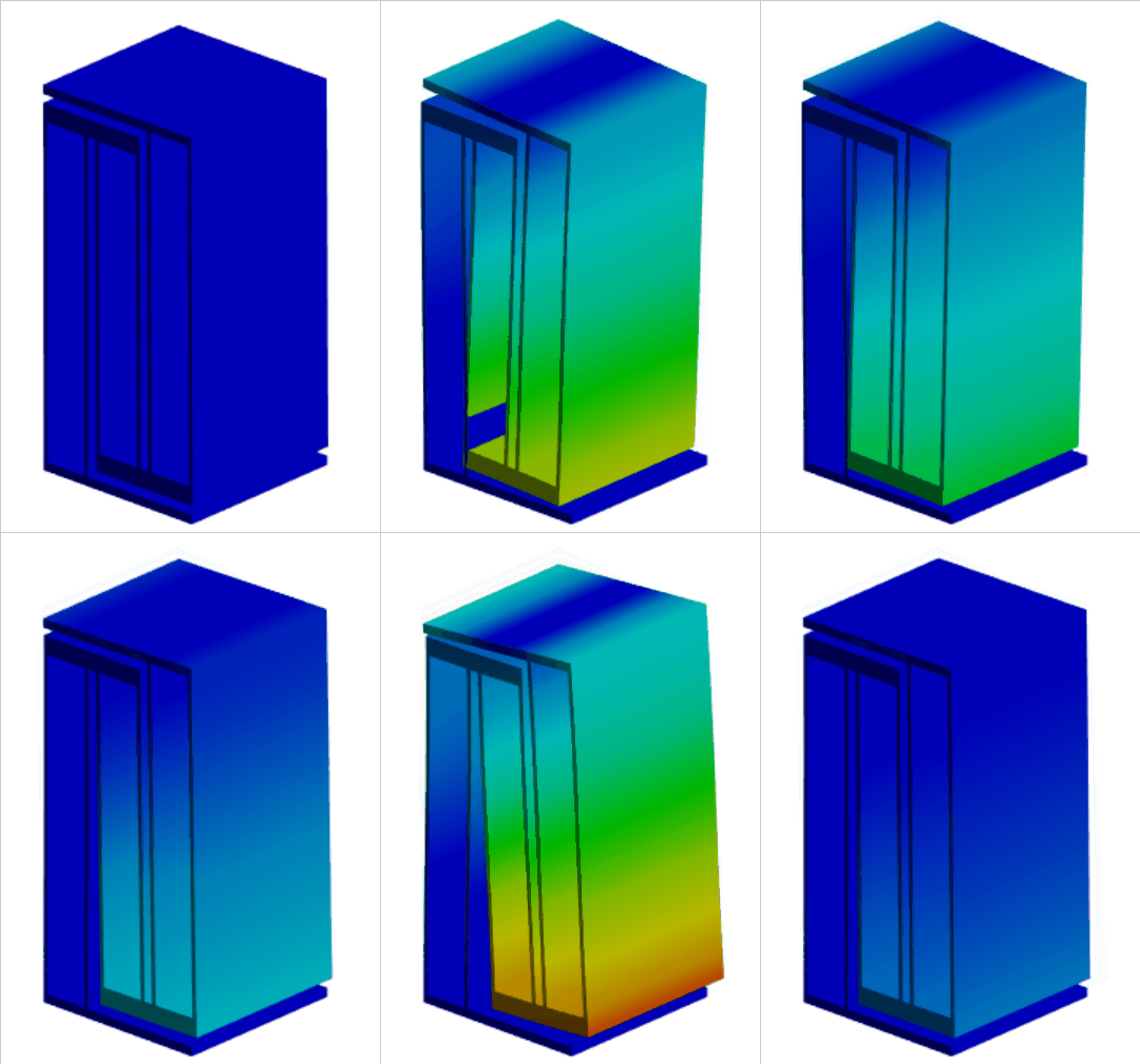
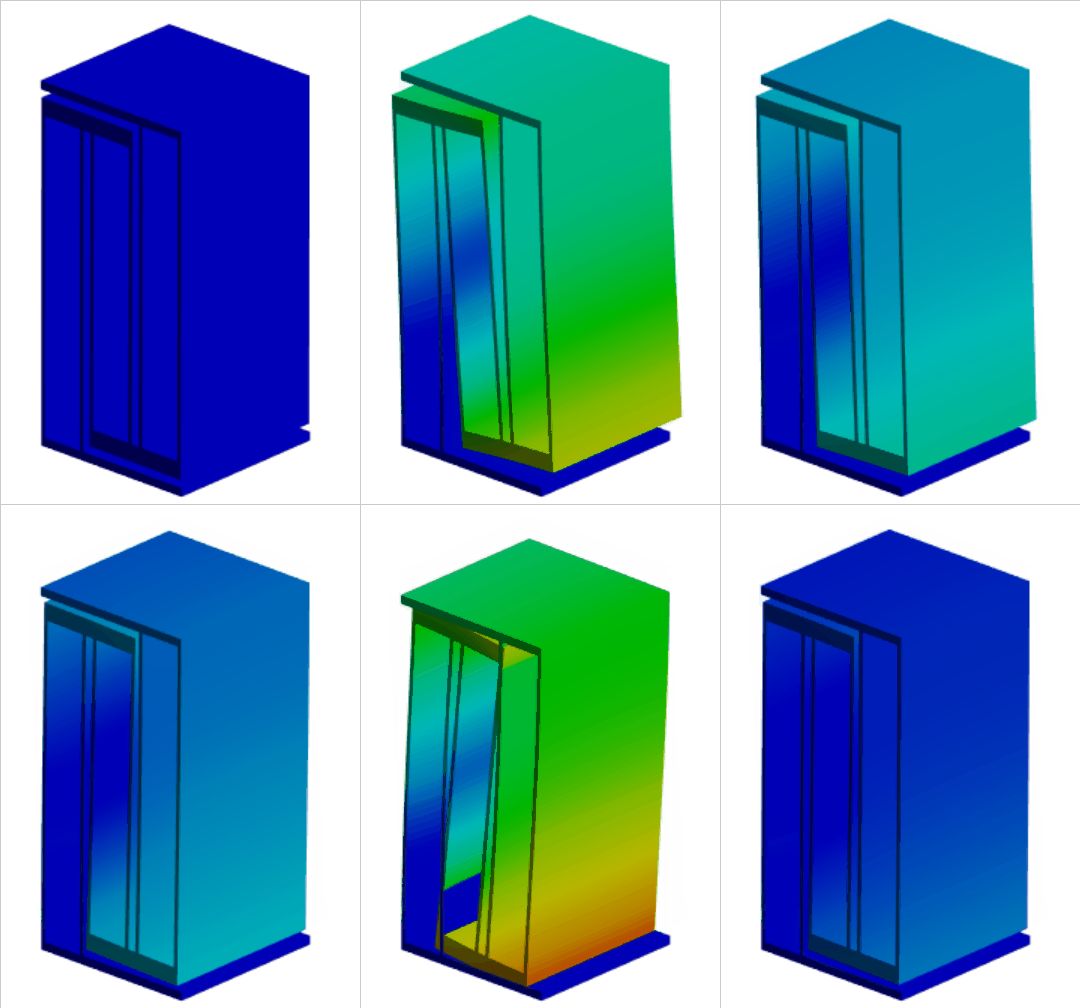
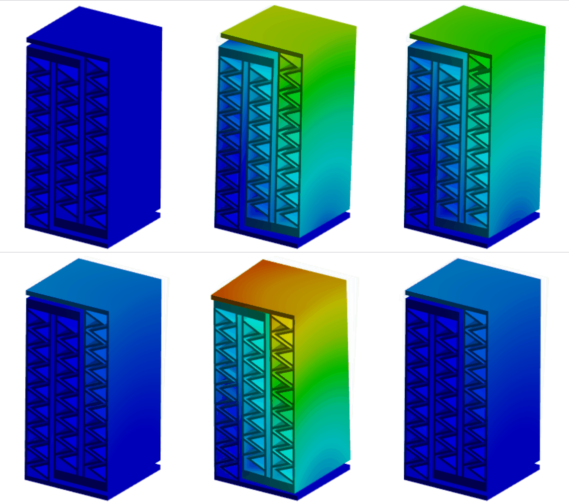
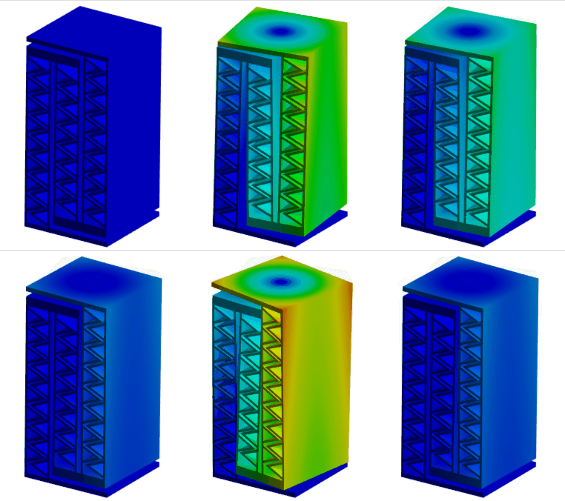
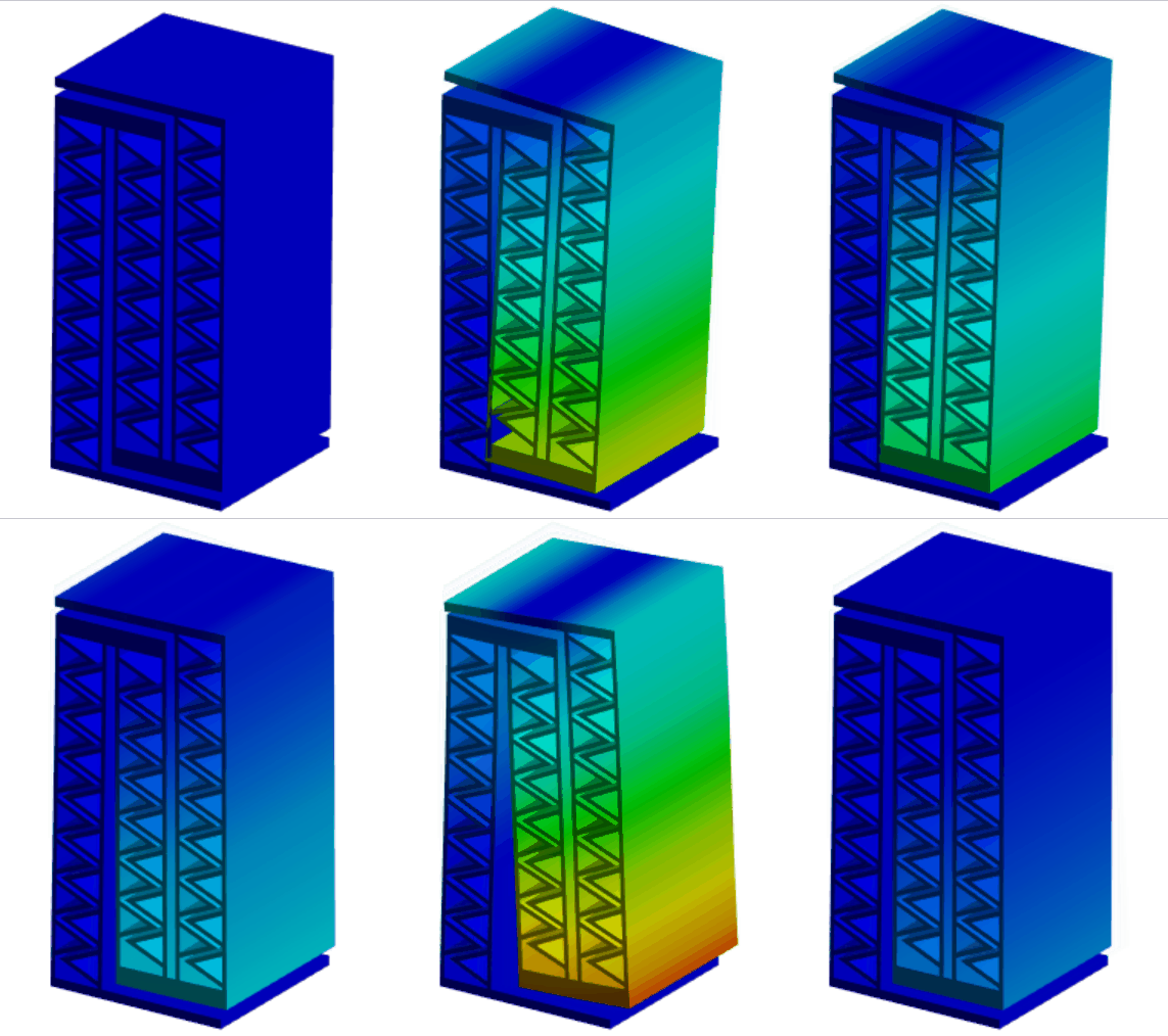
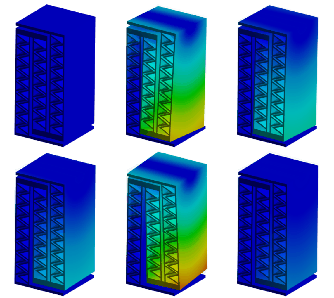
改善前の構造とともに,有限要素解析を用いて固有振動数を計算しました。
改善前
| 1次 | 2次 | 3次 | 4次 | 5次 | 6次 | |
|---|---|---|---|---|---|---|
| 変形モード | ![]() |
![]() |
![]() |
![]() |
![]() |
![]() |
| 固有振動数[Hz] | 25 | 170 | 200 | 583 | 645 | 1426 |
改善後
| 1次 | 2次 | 3次 | 4次 | 5次 | 6次 | |
|---|---|---|---|---|---|---|
| 変形モード | ![]() |
![]() |
![]() |
![]() |
![]() |
![]() |
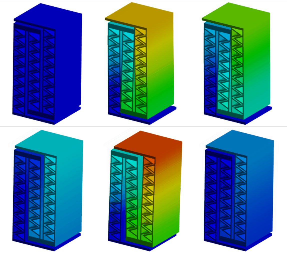
| 固有振動数[Hz] | 35 | 252 | 279 | 598 | 660 | 1780 |
簡易計算結果では樹脂部の質量や厚肉部の変形を考慮していなかったため,特に高次モードにおいて有限要素解析結果との違いが生じています。
改善前後で固有振動数を比較すると,X方向並進運動に関する固有振動数は1.40倍になりました。しかし,Y軸回転運動に対する固有振動数は1.64倍となり,この方向に対して効率的に剛性を向上できていることが分かります。
このように,変形モードを考えた形状を適用することで回転に対する剛性も改善することができます。今回は思い付きで作成した形状なので,各所のパラメータを調整すればより良い構造が得られる可能性もあります。
まとめと課題
スライダー構造において,誘導したい変形に対してのみ低剛性化するには梁を薄くするか長くする必要があり,その際にねじれに対して大きく低剛性化することを説明しました。また,ねじれに対する剛性を向上する方法として,梁の部分に曲げ変形のみが生じやすい構造を適用する方法を紹介しました。
今回は剛性異方性構造について紹介しましたが,実製品として適用するには次のような課題に対して考える必要があります。
- 形状が複雑化したため,製造難易度が高くなった可能性がある。
- 素材の量が増えたため,単価コストや重量が増加する。
- 種々の強度評価を実施する必要がある。
- 微小変形を想定しているため,変形が大きくなると剛性異方性が成り立たなくなる場合がある。
- 幾何公差に対するロバスト性を考慮する必要がある。
これらの対策に対してもいつか紹介できればと思っています。最後までお付き合いいただき、ありがとうございました。もし、不明点や疑問点がありましたら、コメント欄からお気軽にお問い合わせください。可能な範囲でお応えいたします。
Introduction
In the previous article, we computed the behavior of a slider structure in a simplified manner as a structure that is less stiff in only one direction. It was also noted that the slider structure has higher stiffness in the direction of the beam thickness in which the deformation is to be induced, compared to a simple cantilever beam.
In this article, we discuss how to achieve lower stiffness and the challenges faced in doing so.

To achieve lower stiffness and challenges
For lower stiffness in X direction
If the deformation is to be induced in the x-direction, we can make \(S_{11}\), the component of the compliance matrix with respect to the x-direction, larger than the others.
\(\begin{bmatrix} d_x \\ d_y \\ \theta_z \\\end{bmatrix}
= \begin{bmatrix}
S_{11} & S_{12} & S_{16} \\ & S_{22} & S_{26} \\ \text{sym.} & & S_{66} \end{bmatrix}
\begin{bmatrix} F_x \\ F_y \\ M_z \\\end{bmatrix}\)
In the previous article, it was mentioned that the behavior of beams connected in series can be obtained by adding the compliance matrices, and that the deformation can be increased by connecting beams in series.
To increase the ratio of compliance matrix components (such as \(S_{11}/S_{22}\) or \(S_{11}/S_{66}\)), structures with larger ratios must be combined. If \(S_{11}\) is made larger, other deformations must be allowed to increase (\(S_{11}/S_{22}\) and \(S_{11}/S_{66}\) become smaller).
On the contrary, structures with more pronounced stiffness anisotropy cannot be realized by simply changing the beam arrangement, but only by reducing the beam thickness or increasing the beam length. However, there is a limit to how thin the beams can be made, given the buckling strength and manufacturing constraints. (If the structure is allowed to deform under load after fabrication, the QZS structure may provide a solution.)
Connect slider structures in series
To reduce the stiffness in the X-direction without significantly compromising rigidity in the Y-direction or against rotation, modify the geometry as follows
- Increase the design area by changing the Y-directional dimension from 20 mm to 40 mm
- Change the beam thickness from 1 mm to 0.5 mm
- Connect the slider structure in series

The behavior when a directional load of 1 N is applied is shown below. The thin dotted line indicates a cantilevered beam, and the solid line indicates the series structure shown above.

Compared to the cantilever beam, the deformation in the X-direction is larger and the rotation angle is smaller. The displacement in the y-direction is larger, but negligible compared to the displacement in the X-direction.
By allowing a small amount of Y-directional displacement and rotation, the structure can be connected in series to obtain a structure with lower stiffness in the X-direction.
Torsional deformation increases
This is not a happily-ever-after situation. The lower stiffness may cause problems with out-of-plane stiffness that have not been taken into account.
3-dimensional deformation behavior
To account for out-of-plane deformation, it is necessary to consider the behavior in three dimensions. Using the spatial mechanism approach, the calculation can be performed as simply as in the 2D case.
If out-of-plane deformation is also considered, the compliance matrix \([S]\) of a uniform beam becomes
\(\boldsymbol{T} = [S]\boldsymbol{W}\\
\begin{bmatrix} d_x \\ d_y \\ d_z \\ \theta_x \\ \theta_y \\ \theta_z \\\end{bmatrix}
= \begin{bmatrix}
\frac{l^3}{3EI_x} & 0 & 0 & 0 & 0 & \frac{l^2}{2EI_x}\\
0 & \frac{l}{Ebh} & 0 & 0 & 0 & 0\\
0 & 0 & \frac{l^3}{3EI_z} & -\frac{l^2}{2EI_z} & 0 & 0 \\
0 & 0 & -\frac{l^2}{2EI_z} & \frac{l}{EI_z} & 0 & 0 \\
0 & 0 & 0 & 0 & \frac{l}{GJ} & 0 \\
\frac{l^2}{2EI_x} & 0 & 0 & 0 & 0 & \frac{l}{EI_x} \end{bmatrix}
\begin{bmatrix} F_x \\ F_y \\ F_z \\ M_x \\ M_y \\ M_z \\\end{bmatrix}\)
where J is the torsional constant of the beam, and in this case the following equation was used
\(J = \frac{bh^3}{3} \left(1-\frac{192h}{\pi^5b} \sum_{n=1}^{\infty} {1 \over 2n-1}\tanh{(2n-1)\pi b\over 2h}\right)\)
Let \([N]\) denote the coordinate transformation matrix from \(\boldsymbol{W'}\) to\(\boldsymbol{W}\).
\(\boldsymbol{W} = [N] \boldsymbol{W'}\\
\begin{bmatrix} F_x \\ F_y \\ F_z \\ M_x \\ M_y \\ M_z \\\end{bmatrix} = \begin{bmatrix}
\boldsymbol{n_1} &
\boldsymbol{n_2} &
\boldsymbol{n_3} &
\boldsymbol{0} &
\boldsymbol{0} &
\boldsymbol{0} \\
\boldsymbol{L} \times \boldsymbol{n_1} &
\boldsymbol{L} \times \boldsymbol{n_2} &
\boldsymbol{L} \times \boldsymbol{n_3} &
\boldsymbol{n_1} &
\boldsymbol{n_2} &
\boldsymbol{n_3}
\end{bmatrix}
\begin{bmatrix}
F_x' \\ F_y' \\ F_z' \\ M_x' \\ M_y' \\ M_z' \\\end{bmatrix}\)
The stiffness matrix when the beam is moved is expressed as
\([Q] = [N][Q'][N]^\boldsymbol{T}\)
where \(\boldsymbol{n_1}\),\(\boldsymbol{n_2}\),\(\boldsymbol{n_3}\) in the transformation matrix \([N]\) are the unit vectors of X'Y'Z' in each axis direction and \(\boldsymbol{L}\) is the position vector represents the position vector of the tip of the beam.
The behavior of beams connected in series or parallel can also be obtained by adding the compliance and stiffness matrices like in the two-dimensional case.
Natural Vibration Modes
Stiffness anisotropy of a structure can also be understood by looking at its natural vibration modes (depending on the application, this may be easier to consider as a real problem). Lower natural frequency modes indicate lower stiffness.
The natural frequency values and modes can be obtained using the equations of motion with inertia taken into account.
\([M]\frac{d^2 \boldsymbol{T}}{dt^2} + [Q]\boldsymbol{T} = \boldsymbol{W}\)
where `\([M]\) is the matrix constructed by the mass and inertia tensors (\(diag(m,m,m,I_x,I_y,I_z)\)) transformed in coordinates. When the load is zero, the following equation holds for the natural frequency \(\omega_n\).
\([M]^{-1}[Q]\boldsymbol{T} = \omega_n^2\boldsymbol{T}\)
Therefore, by calculating the eigenvalues and eigenvectors of \([M]^{-1}[Q]\), the eigenfrequencies and eigenmodes of 6 degrees of freedom can be obtained.
The table below compares the natural frequencies and eigenvectors for the slider structure alone with a beam thickness of 1 mm treated in the previous article and for the above series structure. The upper part of the structure is 1 mm thick steel (density 7850 kg/m^3). Each eigenvector is normalized to have a norm of 1, so the absolute values of the components are meaningless.
Slider structure

| 1st | 2nd | 3rd | 4th | 5th | 6th | |
|---|---|---|---|---|---|---|
| Natural frequency [Hz] | 284 | 2073 | 3481 | 4922 | 5680 | 7772 |
| dx [m] | 0.97 | 0 | 0 | 0 | 0 | 0 |
| dy [m] | 0 | 0 | 0 | 0 | 1 | 0 |
| dz [m] | 0 | -0.01 | 0 | 0 | 0 | 0.01 |
| θx [rad] | 0 | 1.00 | 0 | 0 | 0 | 1.00 |
| θy [rad] | 0 | 0 | 1 | 0 | 0 | 0 |
| θz [rad] | 0.24 | 0 | 0 | 1 | 0 | 0 |
Serial structure

| 1st | 2nd | 3rd | 4th | 5th | 6th | |
|---|---|---|---|---|---|---|
| Natural frequency [Hz] | 23 | 168 | 309 | 426 | 758 | 1154 |
| dx [m] | 0.90 | 0 | 0 | 0 | 0 | 0 |
| dy [m] | 0 | 0 | 0 | 0 | 1 | 0 |
| dz [m] | 0 | 0 | -0.04 | 0 | 0 | 0.00 |
| θx [rad] | 0 | 0 | 1.00 | 0 | 0 | 1.00 |
| θy [rad] | 0 | 1 | 0 | 0 | 0 | 0 |
| θz [rad] | 0.43 | 0 | 0 | 1 | 0 | 0 |
A comparison of the natural frequencies shows that the series structure is less rigid for each mode. Although Z-axis rotation appears as a first-order mode in both structures, the center of rotation is calculated to be y = 4.0 m and y = 2.1 m, which is quite far from the overall dimensions, indicating that it is almost a translational motion in the X direction. The deformation mode close to the rotation around the Y-axis is a cubic mode for the single structure, whereas it is a quadratic mode for the series structure.
As shown above, when the stiffness is reduced in the X direction, the stiffness with respect to the out-of-plane XY direction is also reduced, especially with respect to rotation around the longitudinal axis.
Torsional properties of slider structure
The reduced stiffness against torsion is due to the characteristics of the slider structure. Compare the torsional properties of a simple cantilevered beam and a slider structure when varying the dimensions. When the thickness or length is changed, the compliance matrix diagonal component \(S_{55}\) with respect to \(\theta_y\) changes as follows

Both structures are shown based on a width of 20 mm, a thickness of 0.5 mm, and a length of 20 mm. The beams of the slider structure were fixed at ±10 mm. When the beam length is increased and the beam thickness is decreased, the slider structure shown by the solid line shows a larger change in \(S_{55}\) than the cantilever beam shown by the dotted line. In other words, when the stiffness in the x-direction is adjusted to be small, the slider structure tends to have larger torsional deformation.
The smaller beam-to-beam distance is also a significant factor in this series structure. The figure below shows the variation of \(S_{55}\) with distance between beams.

The smaller the beam spacing, the closer to a cantilevered beam structure, and the more prone to twisting. To maintain a large beam-to-beam distance, extrusion constraints must also be eliminated.
Higher rigidity against torsion
A slider structure connected in series has low stiffness against torsion, so try to find a way to increase the stiffness against torsion without significantly increasing the stiffness against displacement in the x-direction.
Try applying a structure that is prone to only bending deformation to each beam, as shown in the figure.

The natural frequencies were calculated using finite element analysis, in addition to the structure before the improvement.
Before improvement
| 1st | 2nd | 3rd | 4th | 5th | 6th | |
|---|---|---|---|---|---|---|
| Vibration mode | ![]() |
![]() |
![]() |
![]() |
![]() |
![]() |
| Natural frequency [Hz] | 25 | 170 | 200 | 583 | 645 | 1426 |
After Improvements
| 1st | 2nd | 3rd | 4th | 5th | 6th | |
|---|---|---|---|---|---|---|
| Vibration mode | ![]() |
![]() |
![]() |
![]() |
![]() |
![]() |
| Natural frequency [Hz] | 35 | 252 | 279 | 598 | 660 | 1780 |
The simplified calculation results did not take into account the mass of the resin section or the deformation of the thick-walled section, resulting in differences from the finite element analysis results, especially in the higher-order modes.
Comparing the natural frequencies before and after the improvement, the natural frequency for translational motion in the X direction increased by a factor of 1.40. However, the natural frequency for Y-axis rotational motion is 1.64 times higher, indicating that the stiffness is efficiently improved in this direction.
As shown above, the stiffness against rotation can also be improved by applying a shape that reflects the deformation mode. Since this shape was created on a first thought, it is possible that a better structure can be obtained by adjusting the parameters in various places.
Summary and challenges
In the slider structure, we explained that in order to reduce the stiffness only for the deformation to be induced, the beam must be thinned or lengthened, and that in doing so, the beam is greatly reduced in stiffness against torsion. In addition, as a way to improve the stiffness against torsion, we introduced a method of applying a structure where only bending deformation is likely to occur in the beam section.
Although we introduced stiffness anisotropic structures in this article, it is necessary to consider the following issues when applying them to actual products.
- The difficulty of manufacturing may have raised due to the more complex geometry.
- The unit cost and weight will increase due to the increased amount of materials.
- Various strength evaluations should be conducted.
- Since micro-deformation is assumed, rigidity anisotropy may no longer be valid with large deformation.
- Robustness against geometric tolerances must be considered.
I hope to be able to introduce these measures sometime in the future. Thank you for your patience until the end.