

はじめに
この記事をお読みの皆さんは,日頃からヒンジキャップに弾性エネルギーを蓄えては解放し,解放しては蓄えていることと思います。
双安定性を有するヒンジキャップは,開いた状態と閉じた状態のどちらでも停止することができます。このように2つの異なる安定状態(すなわち双安定性)を有する構造を双安定構造(Bistable Structure)と言います。双安定ヒンジキャップは代表的なコンプライアントメカニズム応用例のひとつです。

本記事では,双安定構造の観点からヒンジキャップを観察した内容を記します。
ヒンジキャップ
ヒンジキャップにはいくつか種類があります。今回は100円ショップで購入した3種類(一般的な名称が存在しないため造語を含めています)のヒンジキャップについて紹介します。
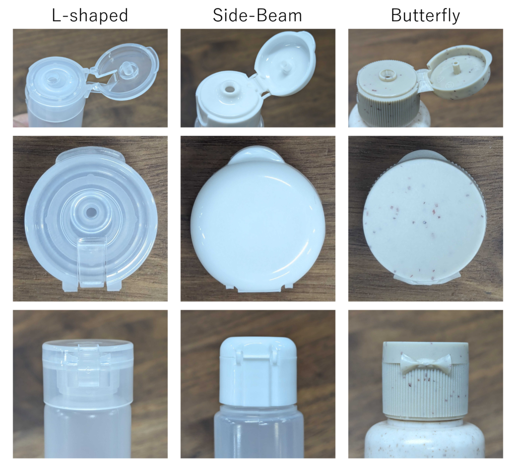
L字型ヒンジ (L-shaped Hinge)
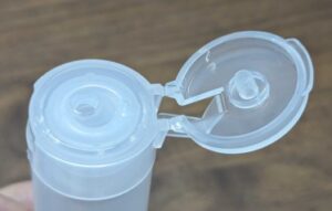
中央部のL字部材(下図の赤点線)が変形することで復元力を生み出しています。
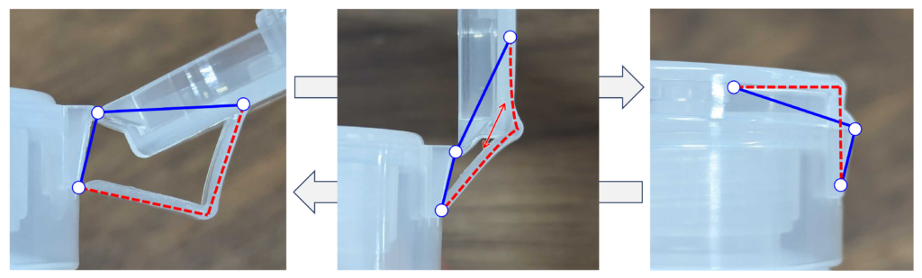
左右の画像は安定した状態を示し,中央の画像は開いた状態から閉じた状態(もしくは逆)へ遷移する途中の不安定な状態を示しています。
青い実線で示す剛ヒンジが直線となる(蓋が90°開いた)状態から,内側に曲がれば閉じる方向へ,外側に曲がれば開く方向へ遷移します。このとき,赤い線で示すL字部材が90°なると復元力がなくなり安定します。中央の遷移状態を蓋が90°開いたときとするため,閉じた状態でもヒンジが蓋の外に位置し凸部を有する形状となります。
単純な機構なので反力や開き角度の調整が容易です。また,他の種類に比べてヒンジ寸法が大きいためモーメント反力を大きくできるという特徴があります。
横梁型ヒンジ (Side-beam Hinge)
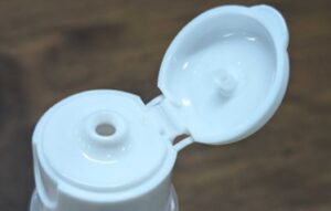
中央部がフラットなヒンジ(下図の青実線)になっており,両側についている細い梁(下図の赤点線)が変形することで復元力を生み出しています。
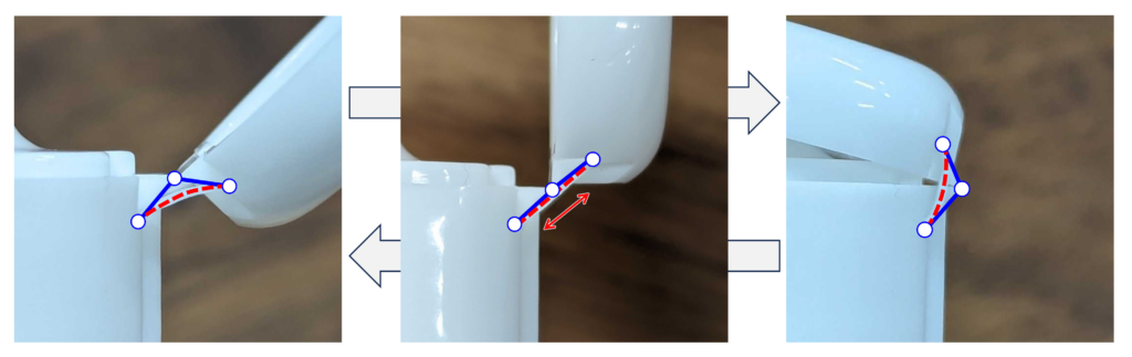
中央の状態では,赤点線で示す梁が伸びて不安定となっています。青色で示すヒンジの角度によってどちらかに倒れ,赤点線で示す梁の引張と曲げによる復元力がつり合う状態で安定します。
上述のL字型よりもヒンジ部がコンパクトになっており外観が目立ちません。フラットヒンジを設けるために蓋が円形から削れた形状になっています。
また,梁軸方向の伸びを利用するため高い応力が発生し,3種類の中では最も耐久性が低い構造と考えられます。
バタフライヒンジ (Butterfly Hinge)
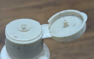
複曲面が裏返ることで双安定性を生み出しています。
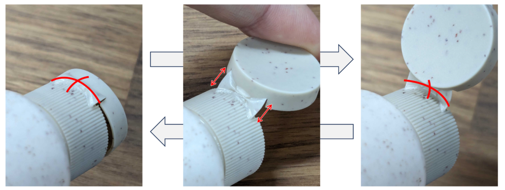
中央の図で示すように,蓋が90°開いた遷移状態ではヒンジが平面に近い状態となります。このとき,側部が伸びることで復元力が生じます。
側部の引張による復元力を利用しているため,上述の横梁型のヒンジを連続的につなげたとも言えます。大きなフラット部分を設ける必要がなく蓋を円形に保ちやすいという特徴があります。広い範囲で荷重を受けているため,横梁型に比べて反力を大きくできること,また耐久性を高くできることがメリットと考えられます。
複曲面構造では,曲げ剛性による復元力よりも面内剛性による復元力が大きい場合,両者が釣り合うときに安定状態となります。ヒンジキャップではガウス曲率が正の複曲面を使用していますが,ガウス曲率が負の曲面を使っても双安定構造になりえます。しかし,遷移状態において側部が圧縮荷重を受け座屈を生じうる,閉じた際に円形状に沿わないといった理由から,ヒンジキャップには用いられていないものと考えられます。
もう少し詳しく
上記までには数式がなくて寂しいので,簡単なモデルを用いてパラメータによる特徴を調べてみましょう。
双安定ヒンジを単純化すると、図のようなバネリンク機構で考えられます。
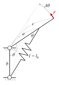
バネ部の長さは初期状態(安定状態)において\(l=l_0\)とします。
荷重がかかる剛リンクが角度\(θ\)にあるとき,バネの長さ\(l\)は
\(l=\sqrt{a^2+b^2-2ab\cos\theta}\)
となります。このとき,回転方向に必要な荷重\(F\)および,バネに蓄えられる弾性エネルギー\(E\)は次のようになります。
\(F=k(l-l_0)\sin\phi\cdot\frac{a}{c}=\frac{kab}{c}(1-l_0/l)\sin\theta\\
E=\frac{1}{2}k(l-l_0)^2\)
例えば,\(a=2,b=\sqrt{2},c=3,l_0=1+\sqrt{3}\)(\(\theta_0=\frac{7}{12}\pi\))のとき,荷重およびエネルギーは次の右図のようになります。左図の安定状態は,弾性エネルギーが極小値をとる点での形状となります。
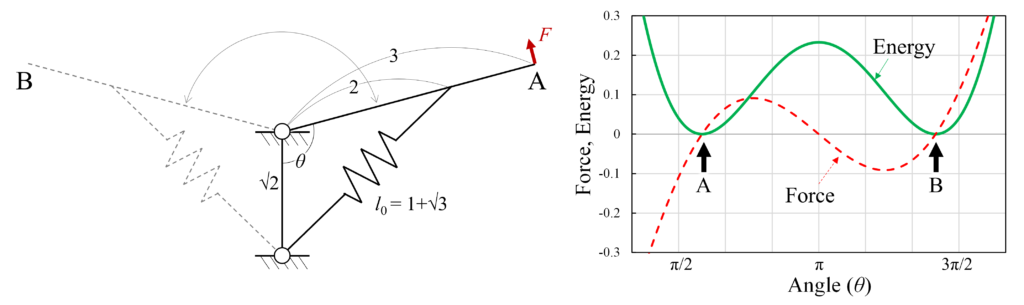
このように,双安定構造ではポテンシャルエネルギー(ここでは弾性エネルギー)が極小値を2つ持ちます。極小値において安定状態となり,極大値を乗り越える十分な外力が与えられるともう一方の安定状態に遷移することができます。すなわち,極大値が大きいほど遷移するためにより大きな外力を必要とし安定状態を保ちやすいと言えます。
今回のバネヒンジモデルにおいて,初期角度\(\theta_0\)および負荷部分までの距離\(c\)が決定している場合を考えます。このとき,弾性エネルギーは\(\theta=\pi\)で極大となり,極大値\(E_{LM}\)は次のようになります。
\(E_{LM}=\frac{1}{2}k(a+b-\sqrt{a^2+b^2-2ab\cos\theta_0})^2\)
括弧内を\(a\)で微分すると
\(\frac{d}{da}\left(a+b-\sqrt{a^2+b^2-2ab\cos\theta_0}\right) = 1+\frac{b\cos\theta_0-a}{\sqrt{a^2+b^2-2ab\cos\theta_0}}\)
ここで,\(\theta \ne 0,\pi\)とすると第2項目は
\(\left(\frac{b\cos\theta_0-a}{\sqrt{a^2+b^2-2ab\cos\theta_0}}\right)^2
=1-\frac{b^2(1-\cos^2\theta_0)}{a^2+b^2-2ab\cos\theta_0}
<1 \\
-1<\frac{b\cos\theta_0-a}{\sqrt{a^2+b^2-2ab\cos\theta_0}}<1\)
となるため,\(\frac{dE_{LM}}{da}\)は常に正であり\(E_{LM}\)は\(a\)に対して単調増加であることが分かります。対称式なので同様に\(b\)に対しても単調増加となります。これにより,\(a\)と\(b\)の寸法は大きいほどエネルギー極大値が大きく,より安定的することが分かります。ただし,現実にはヒンジ部に利用できるスペースが有限であることと,バネ部材を長くすると剛性(バネ定数)が小さくなることから,適切な寸法が決まってくるものと考えられます。
また,バネ部材の初期長さ\(l_0\)も一定のときは,荷重とエネルギーともに\(a=b\)のときに極大値が最大となります。参考までに下図に\(a\)と\(b\)を変えたときの荷重とエネルギーのグラフを示します。
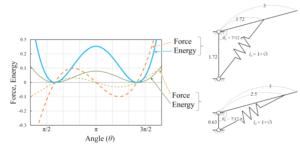
このように,より安定的な双安定構造を設計するためには,剛ヒンジ部の長さ(\(a\),\(b\))をできるだけ同じ寸法で大きくすれば良いことが分かります。最初に紹介したL字型ヒンジでは\(a\)と\(b\)の長さが異なりますが,スペース制約によるものと思われます。
まとめ
双安定ヒンジキャップについて解説しました。これからもヒンジキャップを見かけたときは,弾性エネルギーの変化に思いを馳せながら,その動きを楽しんでみてください。
Introduction.
As you read this article, you probably store and release elastic energy in your hinge caps everyday, and release and store elastic energy in your hinge caps.
A bistable hinge cap can be stopped in either the open or closed state. As such, a structure that has two different stable states (i.e., bistability) is called a bistable structure (Bistable Structure). The bistable hinge cap is a typical example of a compliant mechanism application.
This article describes my observations of hinge caps from the viewpoint of bistable structure.
Hinge Caps
There are several types of hinge caps. In this article, 3 types of hinge caps (coined names are included because common names do not exist) purchased at a 100 yen store are introduced.
L-shaped Hinge
The L-shaped member in the center (red dotted line in the figure below) generates restoring force by deforming.
The left and right images show stable states, while the center image shows an unstable state in the process of transitioning from the open state to the closed state (or vice versa).
The rigid hinge, shown by the solid blue line, transitions from the straight line (lid open 90°) to the closed direction by bending inward, and to the open direction by bending outward. When the L-shaped member shown by the red line reaches 90°, it loses its restoring force and becomes stable. In order to set the transition state shown in the center figure as when the lid is 90° open, the hinge is positioned outside the lid and has the bumps even in the closed state.
It is easy to adjust the reaction force and opening angle because of the simple mechanism of this hinge cap. In addition, the hinge dimensions are larger than those of other types, which allows for a larger moment reaction force.
Side-beam Hinge
The center part is a flat hinge (solid blue line in the figure below), and the thin beams on both sides (dotted red line in the figure below) generate restoring force by deformation.
In the center state, the beams shown by the red dotted lines are stretched and unstable. Depending on the angle of the hinge shown in blue, it will fold to one side or the other, and be stable when the restoring force from tension and bending of the beams shown by the red dotted line is balanced.
The hinge is more compact and less conspicuous in appearance than the L-shaped type described above. In order to provide a flat hinge, the lid has been shaved from a circular shape.
Since it uses the elongation in the beam axial direction, high stresses are generated, and it is considered the least durable structure among the three types.
Butterfly Hinge
The biconvex surface is flipped over to provide bistability.
As shown in the center figure, the hinge is close to flat in the transition state when the lid is opened 90°. At this time, the side extensions generate a restoring force.
Since this hinge utilizes the restoring force generated by the tension of the side portions, it can be said to be a hinge that continuously connects the above-mentioned side-beam type hinges. This type of hinge is easy to keep the lid circular without the need for a large flat area. Since the load is received over a wide area, the advantage of this type of hinge is that the reaction force can be larger and the durability can be higher than that of the side-beam type.
In a biconcave structure, if the restoring force due to in-plane stiffness is greater than the restoring force due to bending stiffness, a stable state is achieved when the two are balanced. The hinge cap uses a compound surface with positive Gaussian curvature, but a bistable structure can also be formed using a surface with negative Gaussian curvature. However, it is not considered to be used in the hinge cap for the following reasons: the side of the cap may buckle under compressive load in the transition state, and the cap does not follow a circular shape when it is closed.
A little more detail.
Since we miss the formulas by the above, let's use a simple model to investigate the characteristics depending on the parameters.
We can simplify the bistable hinge by considering it as a spring-link mechanism, as shown in the figure.
The length of the spring section is given by \(l=l_0\) in the initial (stable) state.
When the rigid link under load is at angle \(θ\), the length of the spring \(l\) is
\(l=\sqrt{a^2+b^2-2ab\cos\theta}\)
The required load in the rotational direction \(F\) and the elastic energy stored in the spring \(E\) are as follows
\(F=k(l-l_0)\sin\phi\cdot\frac{a}{c}=\frac{kab}{c}(1-l_0/l)\sin\theta\\
E=\frac{1}{2}k(l-l_0)^2\)
For example, when \(a=2,b=\sqrt{2},c=3,l_0=1+\sqrt{3}\)(\(\theta_0=\frac{7}{12}\pi\)), the load and energy are as shown in the following right figure. The stable states shown on the left is the shape at the point where the elastic energy reaches local minimums.
Thus, a bistable structure has two local minima of potential energy (elastic energy in this case). The bistable structure is in a stable state at the local minimum, and can transition to the other stable state when a sufficient external force is applied to surpass the local maximum value. In other words, the larger the maximum value, the larger the external force required for the transition, and the easier it is to maintain the stable state.
In the present spring hinge model, consider the case where the initial angle \(\theta_0\) and the distance to the loaded part \(c\) are determined. In this case, the elastic energy reaches its maximum at \(\theta=\pi\), and the maximum value \(E_{LM}\) is
\(E_{LM}=\frac{1}{2}k(a+b-\sqrt{a^2+b^2-2ab\cos\theta_0})^2\)
Differentiating the parentheses by \(a\) yields
\(\frac{d}{da}\left(a+b-\sqrt{a^2+b^2-2ab\cos\theta_0}\right) = 1+\frac{b\cos\theta_0-a}{\sqrt{a^2+b^2-2ab\cos\theta_0}}\)
Here, let \(\theta \ne 0,\pi\), and the second item is
\(\left(\frac{b\cos\theta_0-a}{\sqrt{a^2+b^2-2ab\cos\theta_0}}\right)^2
=1-\frac{b^2(1-\cos^2\theta_0)}{a^2+b^2-2ab\cos\theta_0}
<1 \\
-1<\frac{b\cos\theta_0-a}{\sqrt{a^2+b^2-2ab\cos\theta_0}}<1\)
Therefore, \(\frac{dE_{LM}}{da}\) is positive and\(E_{LM}\) is monotonically increasing with respect to \(a\). Since it is a symmetric expression, it is likewise monotonically increasing with respect to \(b\). This means that the larger the dimensions of \(a\) and \(b\) are, the larger the energy maxima are and the more stable they are. In reality, however, the appropriate dimensions are determined by the finite space available at the hinge and the fact that the longer the spring member is, the lower its stiffness (spring constant) becomes.
Also, when the initial length of the spring member \(l_0\) is also constant, the local maxima of both load and energy are maximum when \(a=b\). For your reference, the graphs below show the load and energy for different values of \(a\) and \(b\).
Thus, it can be seen that to design a more stable bistable structure, the lengths of the rigid hinges (\(a\) and \(b\)) should be as large as possible with the same dimensions. The lengths of \(a\) and \(b\) are different for the L-shaped hinge introduced in the first example, but this may be due to space constraints.
Summary.
I have described bistable hinge caps. Whenever you see a hinge cap, please enjoy its movement by contemplating the change in elastic energy.
