
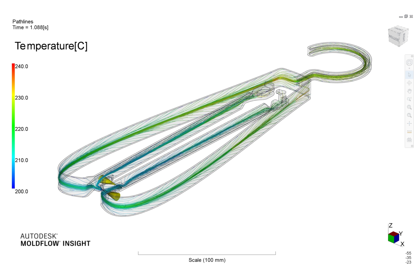
はじめに
Nature Architects では、メタマテリアルを活用した製品設計アルゴリズムを開発しています。私たちはこれらをデリバリーやコスト、品質の観点で現実的に量産可能なものにすることを目指しています。
本報では「折りたたみハンガー」を事例に、生産設計の進め方について解説します。「折りたたみハンガー」においては、コンプライアントメカニズムを応用した新しい構造・機能について提案しました。私たちは第1部で解説した機能設計と同時並行で生産設計を進めました。
第2部では、提案した機能を既存の量産技術、ここではプラスチックの射出成形で実現するための設計について、基本的な手順を示します。
材料、条件、用語など
解析ツール:
- Moldflow Insight 2023(本報ではMoldflowと略す。)
材料材料
- POM、Duracon M90-44(Polyplatics)
- 熱伝導率 \(k\) : 0.24 \(W/mK\)
- 比熱 \(c_p\) : 2,000 \(J/kg K\)
- 密度 \(\rho\) : 1,300 \(kg/m^3\) (溶融時)
- 取出可能温度 \(T_e\) : 143 \(^\circ C\)
成形条件
- 溶融温度 \(T_i\) : 200 \(℃\)
- 金型温度 \(T_d\) : 80 \(℃\)
- 射出率 \(Q\) : 50 \(cm^3/s\)
- 充填時間 \(t_f\) : 1\(s\)
- VP切替 : 自動計算(Moldflow)
- 保圧力 \(P_h\) : 充填圧力の80%
- 保圧時間 \(t_h\) : 10s
- 冷却時間 \(t_c\) : 自動計算 (Moldflow)
射出成形機
- 最大射出圧力 \(P_{max}\) : 180 \(MPa\)
- 最大型締め力 \(F_{max}\) : 7,000 \(ton\)
実用性の概略検討
実用的な量産工法として射出成形を用いることにします。まず最初に、コストを意識しながら加工の可否を検討します。この段階は次の3項目についての大まかな確認であり、この段階を経て設計変更したもので詳細検討を行います。
- 溶融プラスチックは金型内に充填できるか?
- 製品の厚みは適切か?
- 製品は金型から抜くことができるか?
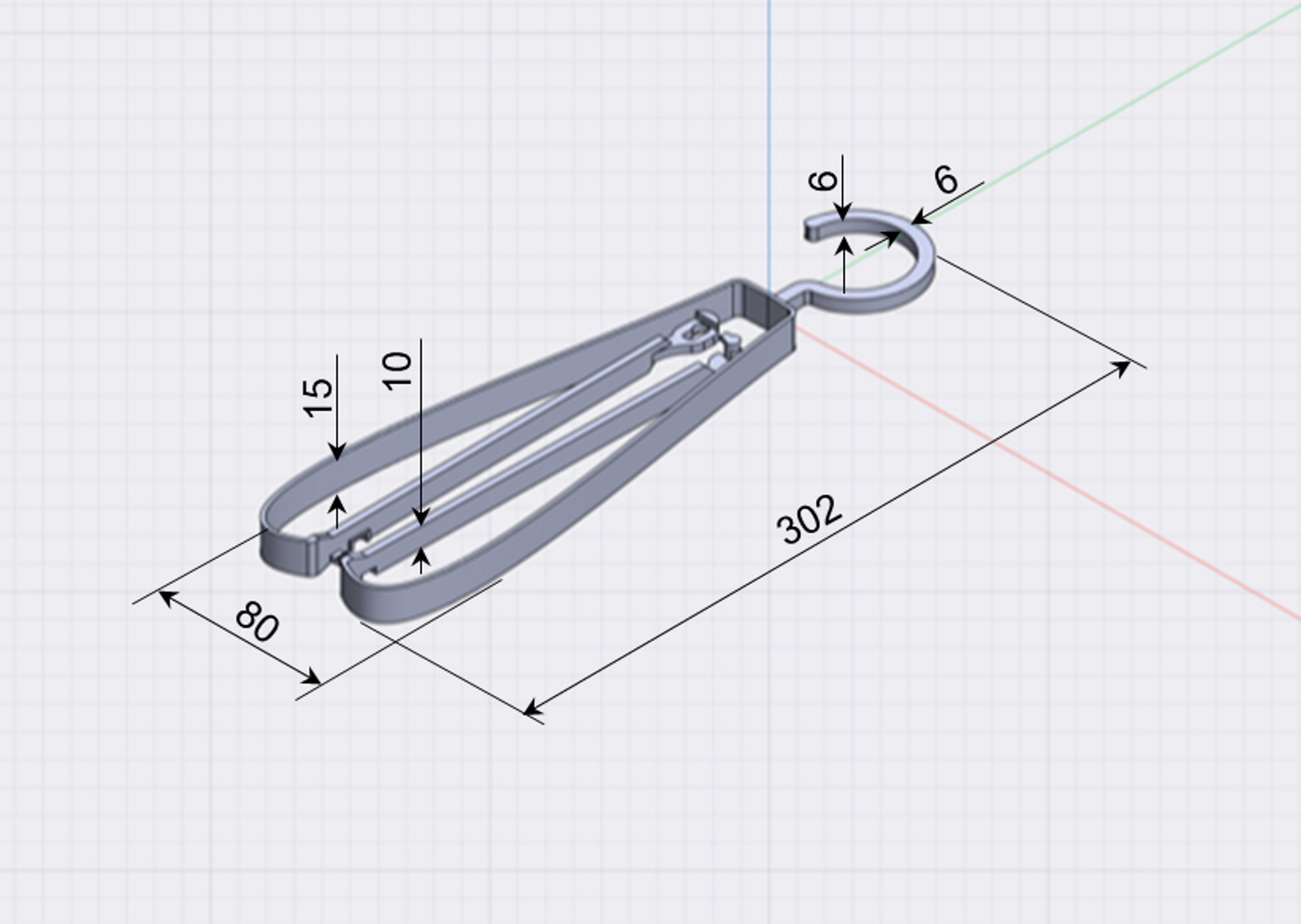
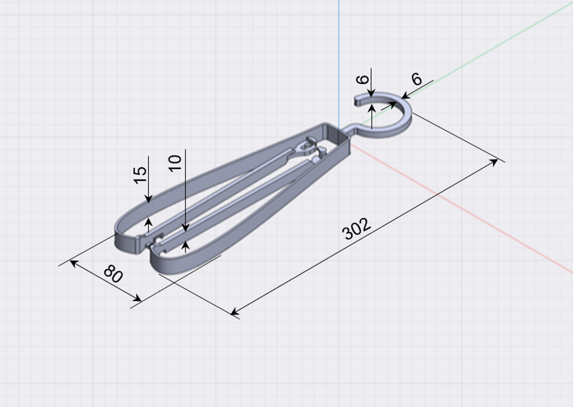
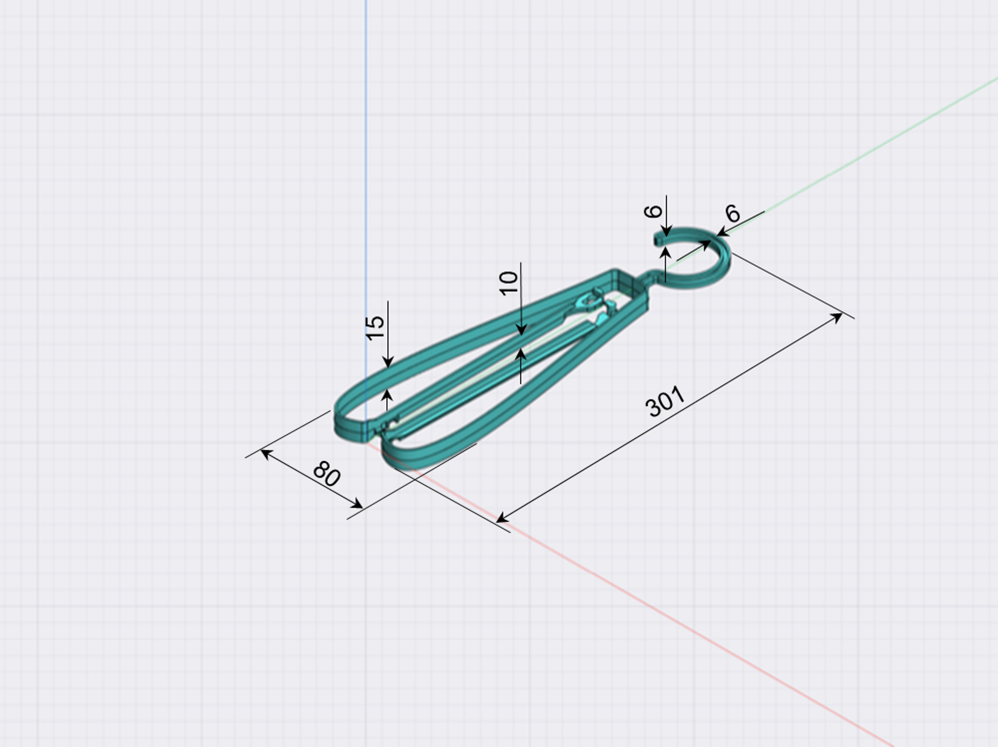
第1部で解説した折りたたみ構造について、その初期形状、寸法を下図に示します。
-
溶融プラスチックは充填可能か?
-
部品の全体の大きさ、すなわち代表的な流動長に対して薄すぎる形状はないか?
流動長約400mm(ゲート位置により異なる)に対して、厚みは最小で2.2mmで、極端に薄いとは言えません。従って、溶融プラスチックの充填は可能と判断できます。いっぽうで、厚みが最大で6mmの部分があり、さらに厚みを減らすことも可能です。
-
-
肉厚は適当か?
- 成形加工時間が長すぎないか?
-
厚みは小さくできるか?
フック部で6mmと厚いために、射出成形プロセスにおける「冷却時間」が長くなることが予測できます。厚みを小さくする必要があります。
平板における非定常熱伝導から、冷却時間は次式で表されます。(参考文献:Rao,Natti S.: Design Formulas for Plastics Engineers, Hanser, Munich(1991) p.50 )
\(t_c = \frac{1}{\alpha} \Bigl(\frac{h}{\pi}\Bigr)^2 \space ln \Bigl[ \frac{4}{\pi} \space \frac{T_d - T_i}{T_d - T_e} \Bigr]\)ここで、\(t_c\) : 冷却時間、\(\alpha\) : 熱拡散率、\(h\) : 肉厚、\(T_d\) : 金型温度、\(T_i\) : 射出される溶融プラスチック温度、\(T_e\) : 取出可能温度であり、熱拡散率は次式で表されます。
\(\alpha = \frac{k}{\rho \space c_p}\)ここで、\(k\) : 熱伝導率、\(\rho\) : 密度、\(c_p\) : 比熱。
冒頭に書いた物性値、成形条件より冷却時間を求めます。最大肉厚 \(h\) = 6mmのフック部に対して、離型可能(金型から部品の取り出しが可能)な状態となる時間は、上式より、冷却時間は
\(t_c\) = 35s
と予測できます。
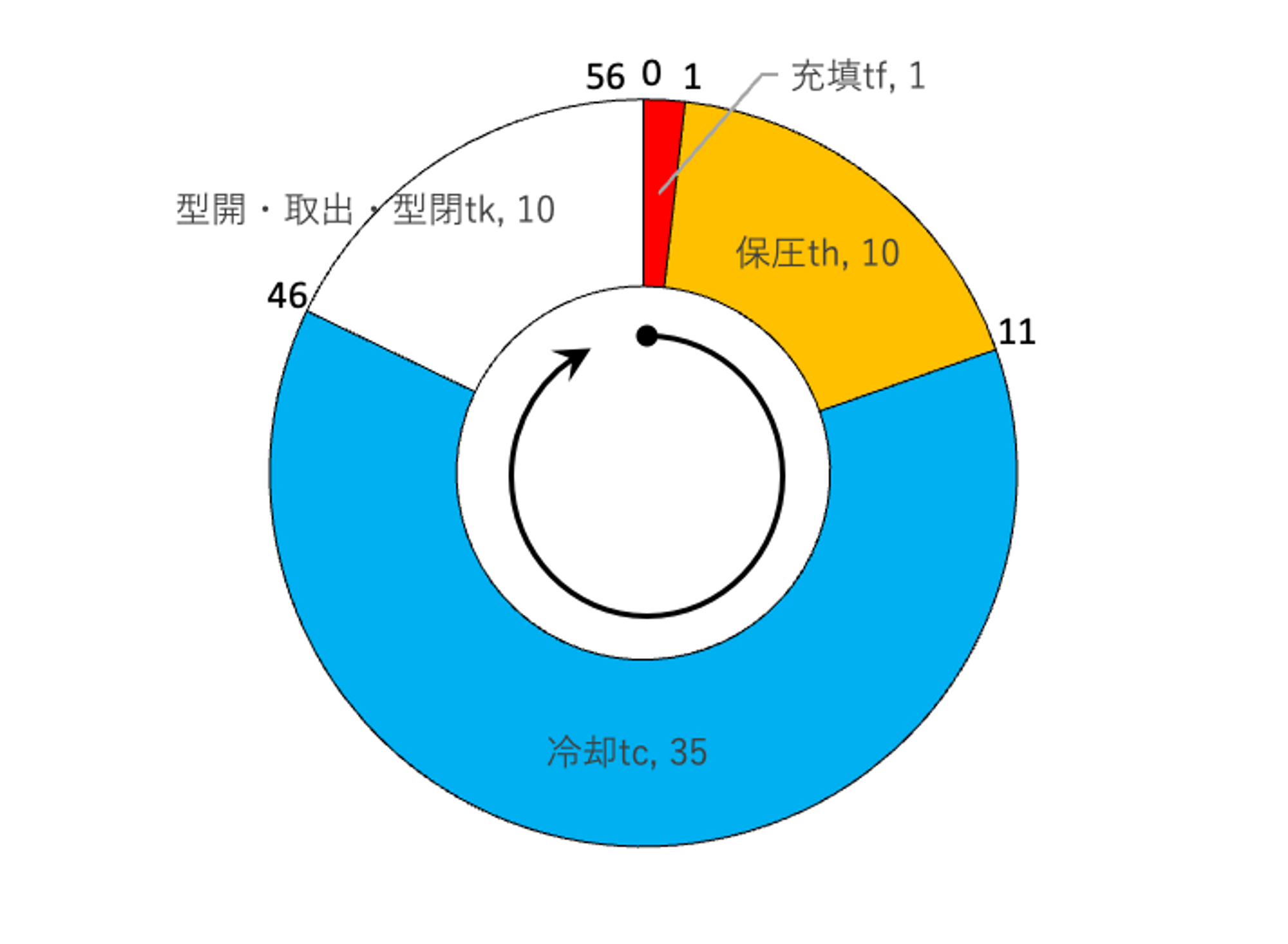
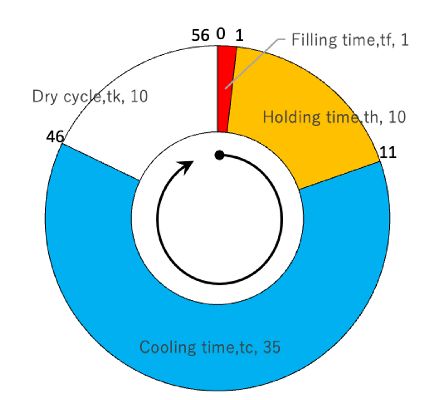
充填時間 \(t_f\) = 1s、保圧時間 \(t_h\) = 10s、 型開~型閉の時間 \(t_k\) = 10sとすると、成形サイクルタイムは、上記の合計であり、
\(t_{cycle}\) = 約56s
と予測できます。
補足 : サイクルタイムの予測について。
厳密には、溶融した高温のプラスチックは充填開始時点から金型壁面に接して冷却が始まっています。充填過程においては、冷却よりも入熱が支配的なので、充填完了後の保圧過程から冷却が開始すると仮定するのは実用的です。また、保圧過程は冷却により収縮していく溶融プラスチックを補充することを目的にしており、すなわち熱流入が継続されます。保圧時間 \(t_h\)=10sとしていますが、これは成形機での機械制御の設定であって、熱流入はその途中で止まる可能性もあります。したがって、実際の冷却時間は保圧時間を含めると考えることもできます。
しかしながら、この計算式では入熱は考慮しておらず、厳密に冷却に要する時間を見積もることはできません。すなわち上記の理論式で推測できる成形サイクルタイムは 46〜56s の範囲にあり、予測にはばらつきがあると認識すべきです。仮に保圧時間の半分を採用すると、サイクルタイムは 約51s と見込むこともできますが、初期検討では保守的に見積もることにします。型開から型閉までのいわゆる「ドライサイクル \(t_k\)」についても設備機器の設定で高速化が可能ですが、ここでは同様に保守的に見積もっています。
次に、Moldflow による計算結果を示します。Moldflowによる計算では、入熱と冷却を連成して計算するので、より現実的な予測となっています。離型可能となる十分に冷却される時間は、次のように計算されました。
\(t_f + t_h + t_c\) = 42s
これより、成形サイクルタイムは約52sと予測できます。
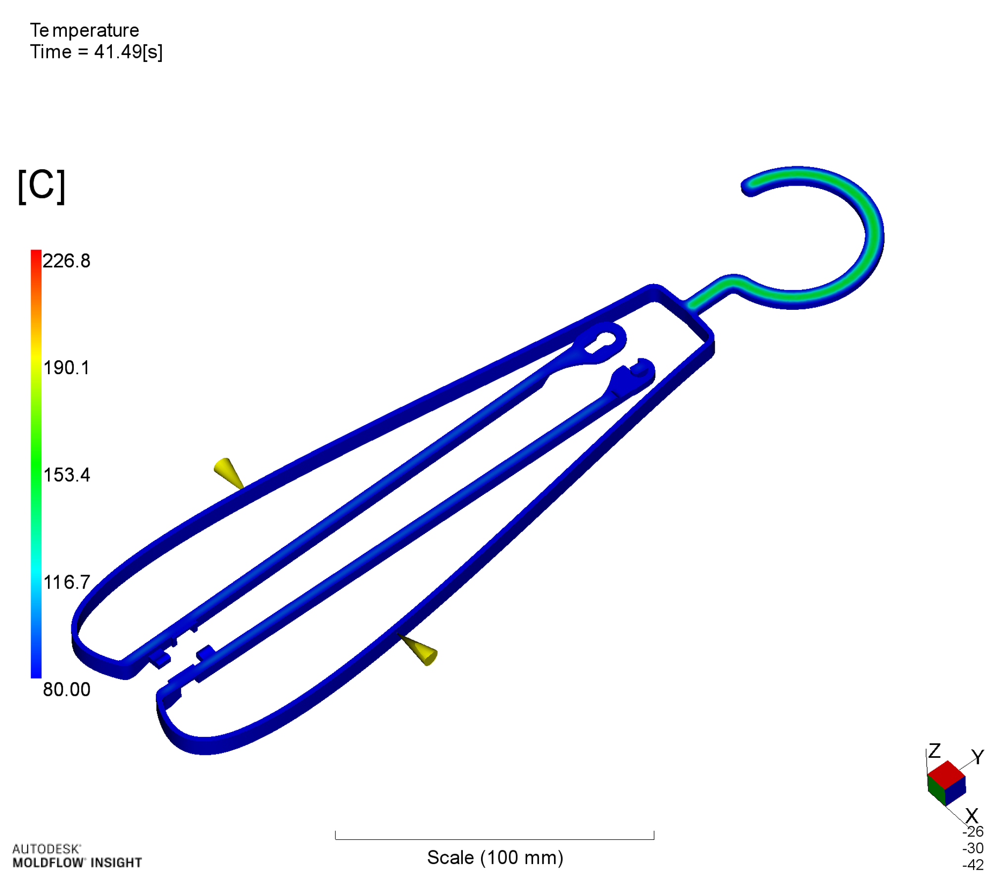
離型可能時間における温度分布(z方向中央の断面)を示します。これより厚みの大きいフック部の温度が高い、すなわち冷却に多くの時間を要することがわかります。逆に、この部分の厚みを小さくすることで、サイクル時間を短縮することができます。
 離型可能時間における温度分布(断面)
補足:上述した理論式とMoldflowでの(今回の)計算ではどちらも、厚み方向の温度がすべて\(T_e\)に到達した場合(100%固化した場合)に離型可能としています。しかしながら実際には、例えば内部が高温で溶融状態にあっても表層の固化が進んで離型可能な場合もあります。100%固化していなくても成形不良なしに離型可能な金型設計を進めることも重要です。具体的には、エジェクタピンを適正に配置すれば、取出し時に無理な力がかからず、変形させずに取り出すこともできます。
ただし、離型時間を変えることによって部品内で冷却状態に差が生じることに注意が必要です。特に結晶性プラスチックでは結晶化度が変わり、その結果収縮率が変化します。収縮率の変化は成形品の寸法、そり変形に影響し、商品設計時点で予測していなかった成形不良発生の可能性があります。手戻りをなくすためにも、商品の機能設計と生産設計の同時進行は重要と考えます。
この商品に求める機能(第1部参照)から、直線部とフック部には一定の剛性が必要です。したがって、サイクルタイム短縮のために単純に厚みを小さくするのではなく、例えばH字状の断面形状とするような形状(肉盗み)の採用が必要です。これにより、冷却時間を短くするとともに、一定の剛性を確保することができます。
-
金型から成形品は抜けるか?
- アンダーカットとなる形状がないか?
-
抜き勾配はあるか?
この部品(ハンガー)を床面に置いた状態の平面をxy面とします。部品は金型をz方向に開いて取り出す(離型する)ように配置します。この部品はパーティング面(PL:パーティングライン)をxy平面、z方向の中央(z=0)とします。z方向が抜き方向であり、部品を離型させるためには第一に「アンダーカット」形状がないことが求められます。アンダーカットがあっても、金型にスライドコアを設けることで離型可能とすることはできますが、金型が高価になることから、できるだけアンダーカットのない形状設計をしたいところです。この部品の初期検討段階から、すでにアンダーカットのない設計となっています。
さらに、離型時の成形不良を起こさせないために、適正な「抜き勾配」を設けることは必須です。一般に抜き勾配は0.5または1度以上とします。初期構想では抜き勾配を設けていないので、設計変更が必要です。
補足:射出成形においては、金型の可動側(型開時に金型でエジェクタピンの配置される)に成形品が残っている必要があります。この商品はz方向中央から+z、-z方向に鏡面対称ですので、同じ離型抵抗であるならば、具体的には同じ抜き勾配としたなら、成形品を可動側に確実に残すことができません。この不安定さを避けるためには、例えば固定側の抜き勾配を可動側よりも大きくすることでこれを実現します。
しかし、そうするとz方向の対称性が崩れてしまいます。この商品の機能として、対称性が崩れる影響度合いを確認しておく必要があります。本報では、対称性が崩れることによる商品機能への影響を検討していません。
射出成形について考慮した設計案
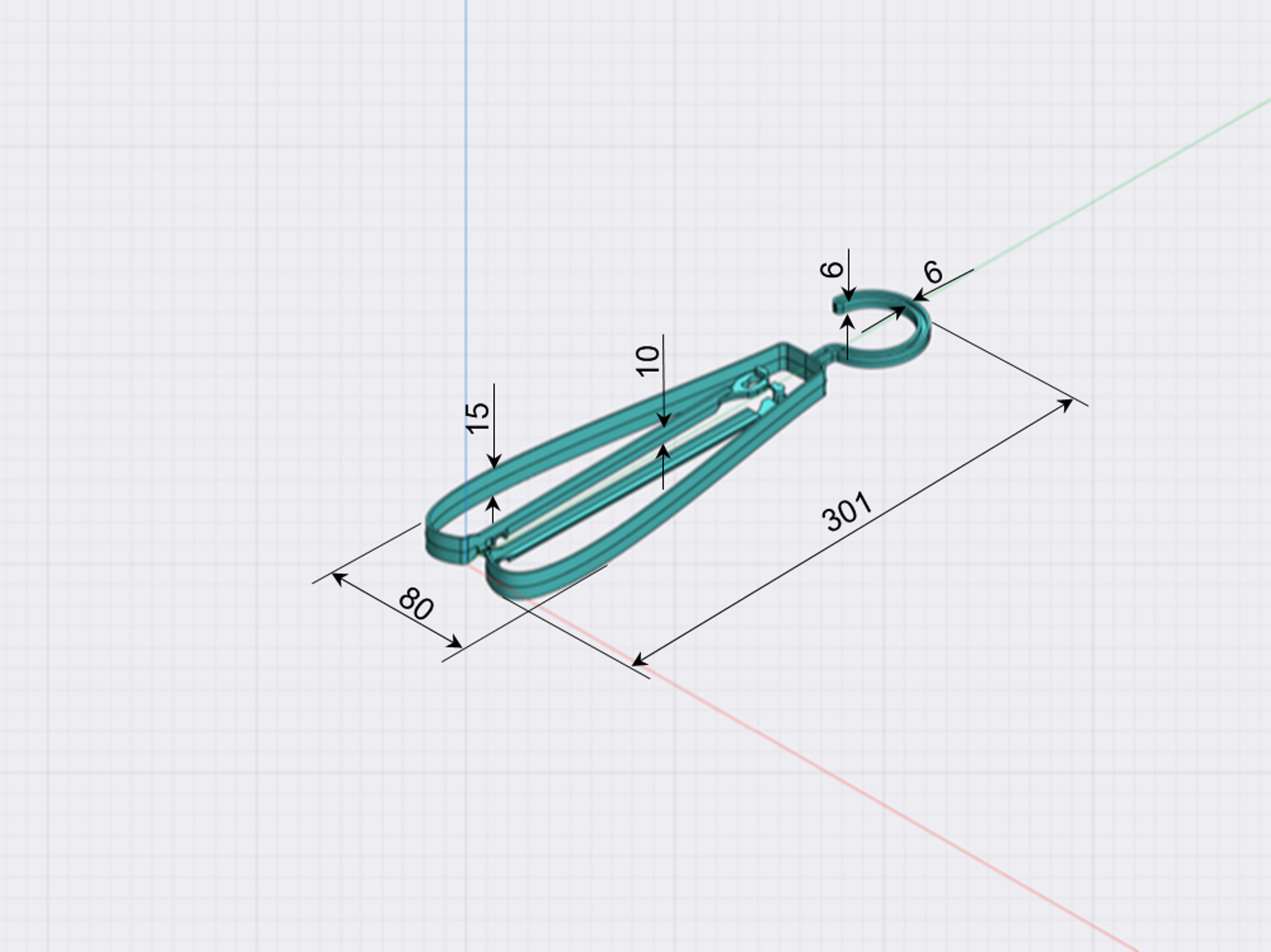
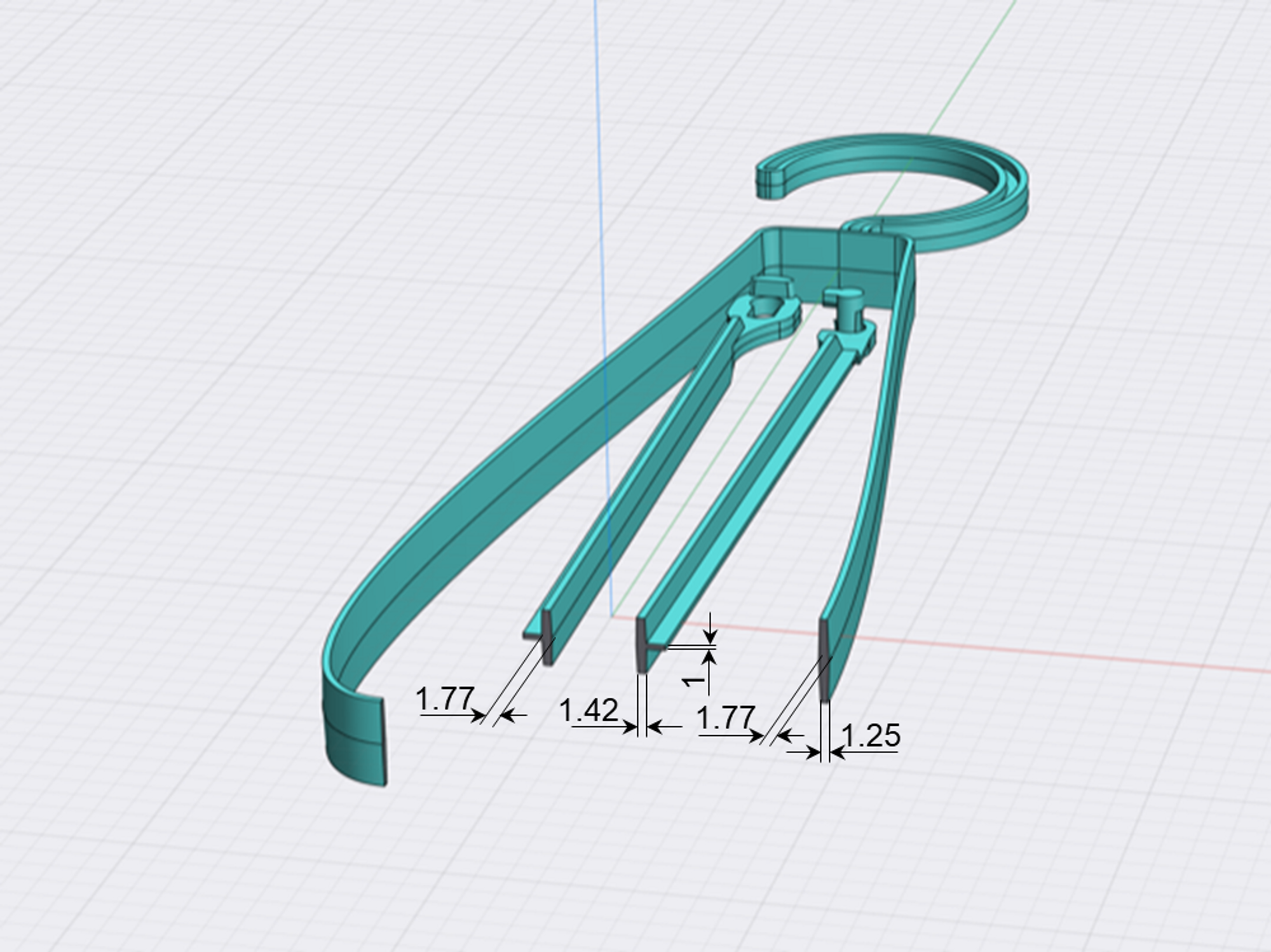
前節で説明した要件に配慮した設計案を示します。フック部断面はH字状に、直線部はT字状にすることにより、薄肉化とともに必要な剛性を確保する形状としています。
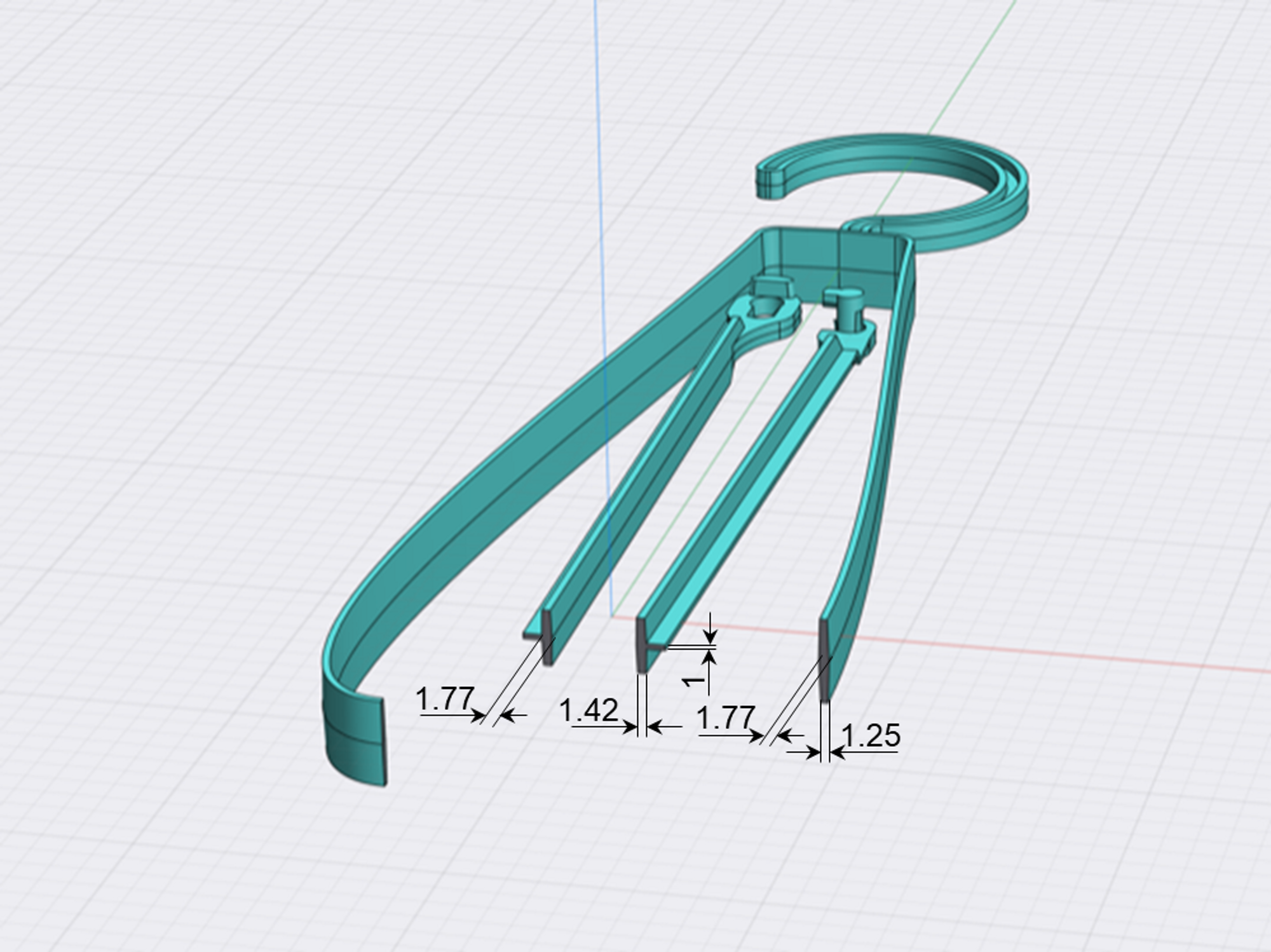
同設計案について一部の断面寸法を示します。z方向中央より上下に抜き勾配を設定。T字部リブ(図中、横に突き出している部分)の厚みは、後述する成形でのそり変形を極小化するための変数とし、初期値を1mmとしています。なお、リブ厚みを1~2mmで変化させても設計意図を満たすことが事前の検討により確認できています。
成形加工性の評価
ここまでで、射出成形での量産実現性を考慮した形状を決定できました。次に、Moldflowを用いて成形不良の発生がないかの確認を進めます。
簡略化:ここでは、ランナーは配置せず、ゲートからの溶融プラスチックの充填だけで評価します。すなわち、仮に複数のゲートを設けるとしたら、それらより同時かつ均等に分配された溶融プラスチックが充填されるものと仮定することになります。これは、次のステップである金型設計にて、ランナーバランスを適正に設計することを期待するものです。同様に金型冷却管も、この段階では配置しません。すなわち、溶融プラスチックが接する金型壁面から均一に冷却されることを仮定することになります。実際には、ハンガー内側を構成する部分については、相対的に冷却しにくいことが予想されます。金型設計においてできるだけ均一冷却となる冷却管レイアウトが実現できることを期待した検討となります。実際には、冷却管を配置できないところもあり、不均一な冷却によりそり変形が大きくなることは予測できます。すなわち、形状修正など設計の手戻りが発生することを認識して、検討を進めることになります。
以下、成形不良現象を想定しながら、計算結果を確認していきます。
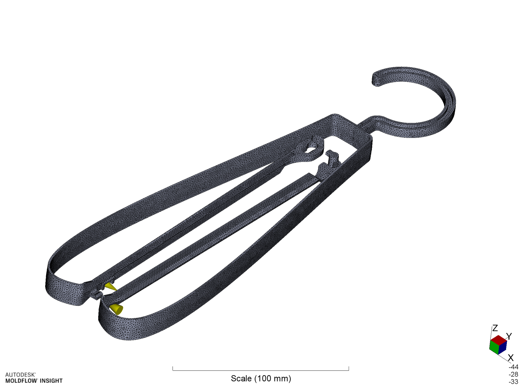
計算に用いたメッシュ(表面のみ表示)を示します。図の左下部のコーンで示した2つの位置をゲートとしています。実は、弓部に2箇所のゲートを配置することにより、3箇所の最終充填位置(流動末端)への同時充填が実現できます。しかしながら、この弓部が薄肉であること、直線部に対する充填・保圧を十分とする(これにより、直線部の収縮を小さくする)ことを意図して、この2つのゲートとしました。
1) 未充填不良(ショートショット)は起こらないか?
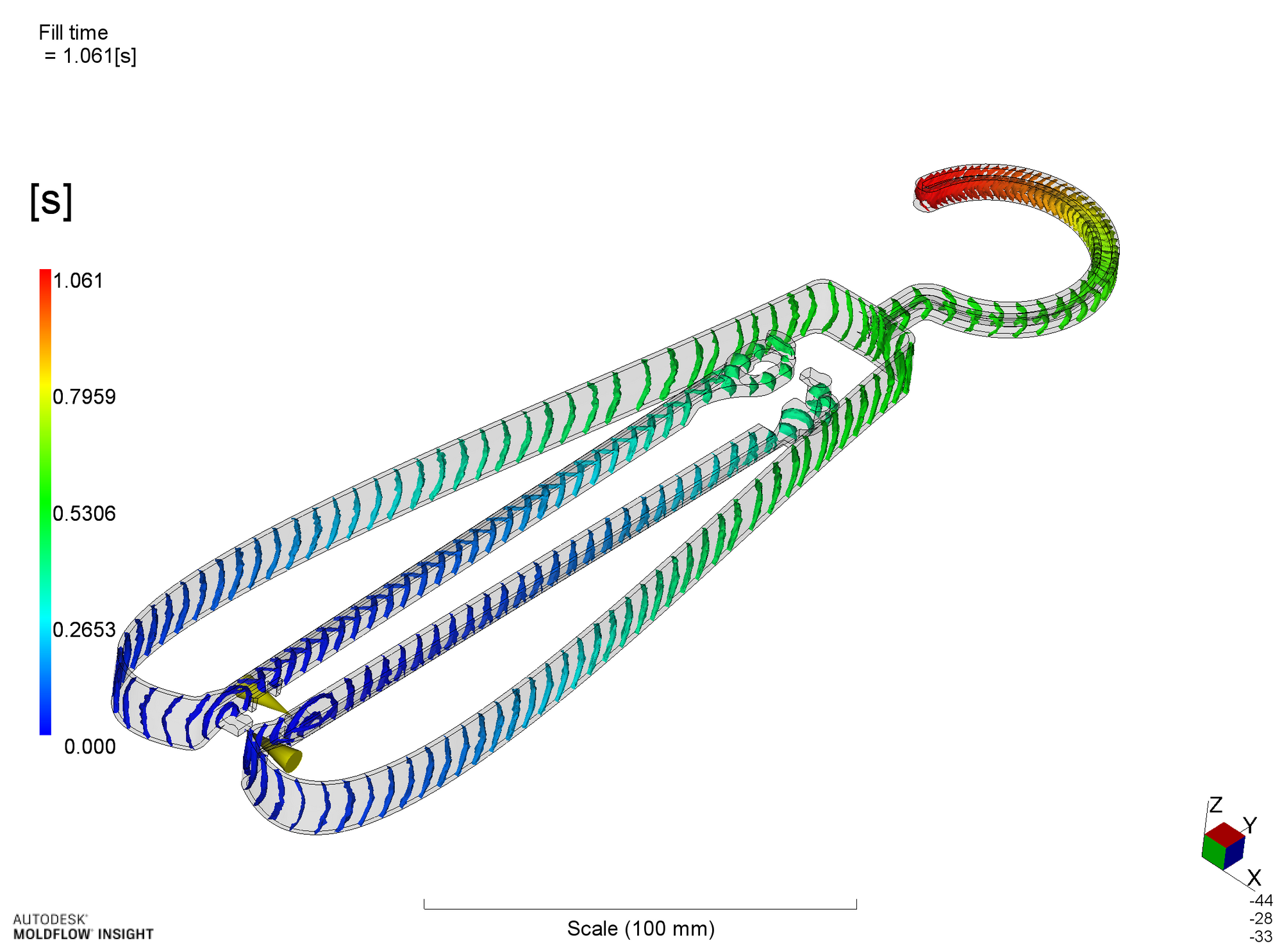
充填末端となる3か所への同時充填は実現できていませんが、射出率を50\(cm^3/s\)と比較的高くとったこともあって、未充填不良の発生はありません。
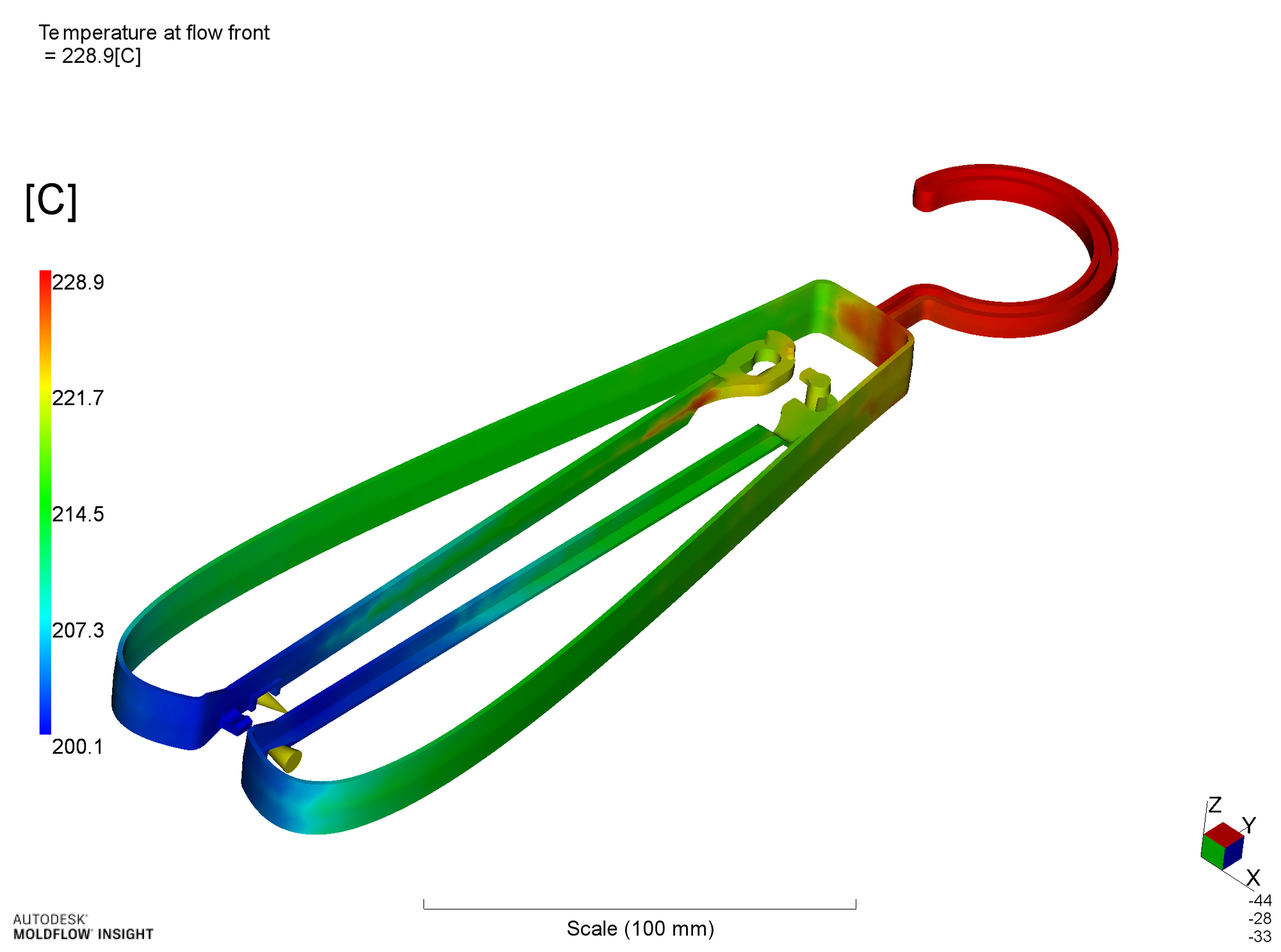
フローフロント(充填中の流れの先端)の溶融プラスチックの温度分布を次に示します。充填途中での温度低下が大きい場合は、固化して未充填不良となますが、本件では温度低下は認められません。逆に、高粘性流体であるがゆえに、せん断発熱が起こり、流入温度である200℃より高温となっています。
2) 強度が低下するウェルドラインの発生はないか?
ウェルドライン発生位置を示します。
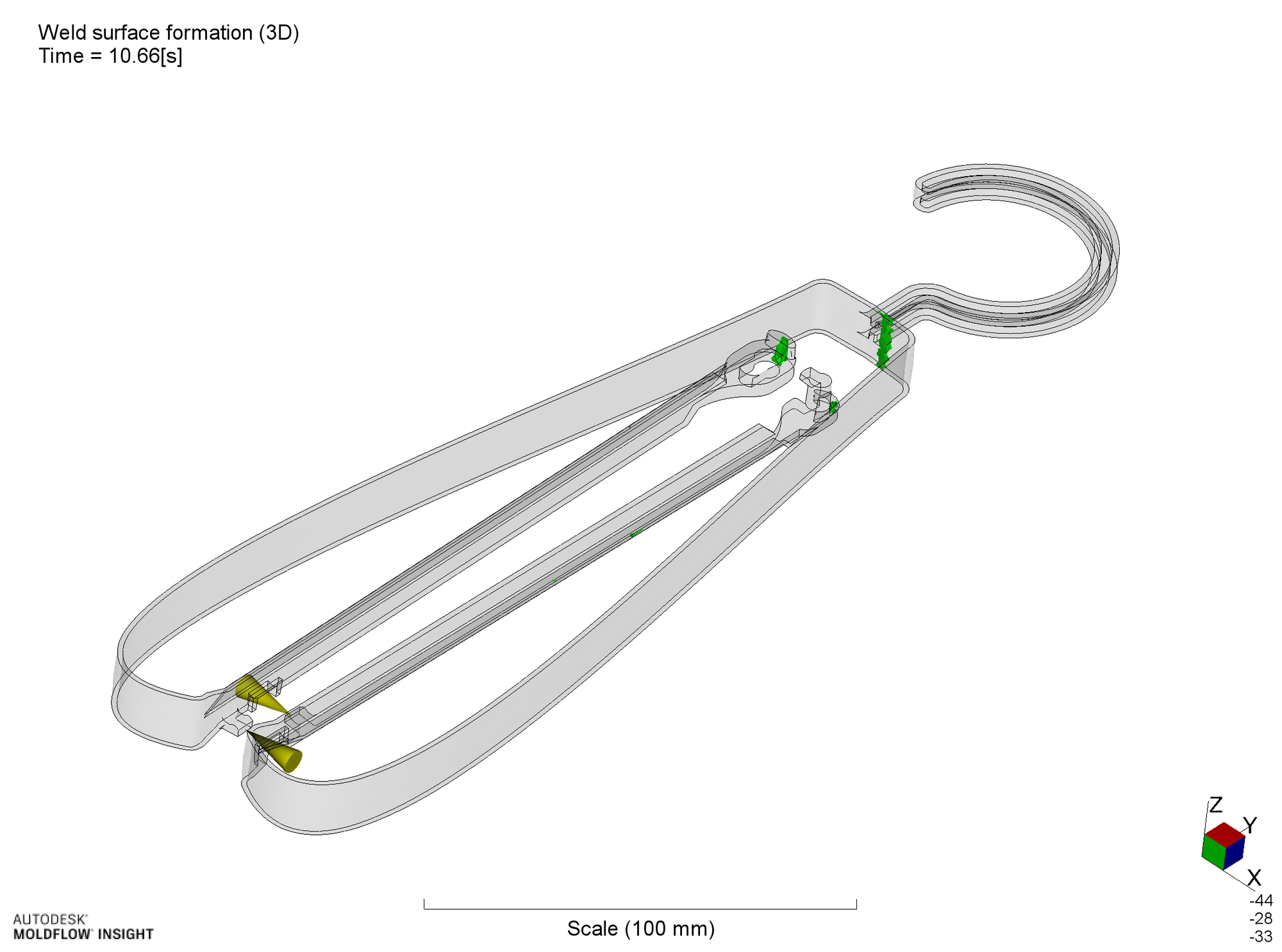
直線部の両端にウェルドラインの発生が予測されます。特に孔側(図の左側)については、孔を形成する部分を迂回する流れの会合が起こります。ここについては、充填末端であることから、速度変化によるウェルドラインの強度低下抑制(後述)を期待できません。
商品機能として、この穴部を末端側に引っ張るような力は作用しないので、強度低下があっても問題はないことが期待されます。期待しますが、一般にウェルドライン部の強度低下を定量的には予測できませんので、実際に作成して試験を行い、強度低下が無視できないならば改善が必要となります。本報告では、ここまで言及しません。
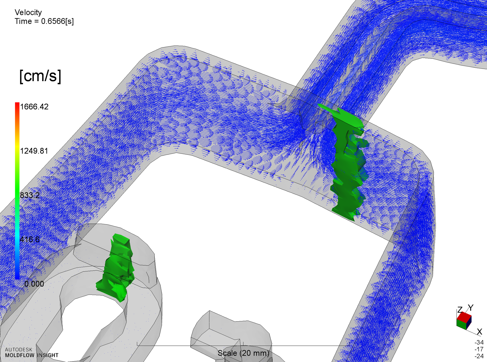
フック付け根付近には、左右の弓部からの流れが会合しています。ここがウェルドライン発生位置と予測できますが、ここは流動末端ではなく、会合後にフック部への流動が継続します。衝突部では図の右から左への逆流も起こって、さらに流動が継続し、高分子の絡み合いが特に内層部で起こります。これにより、この部分の強度は大きく低下しないと考えられます。
確認のために、流速の変化を下に示します。
3) 冷却時間は適正か?
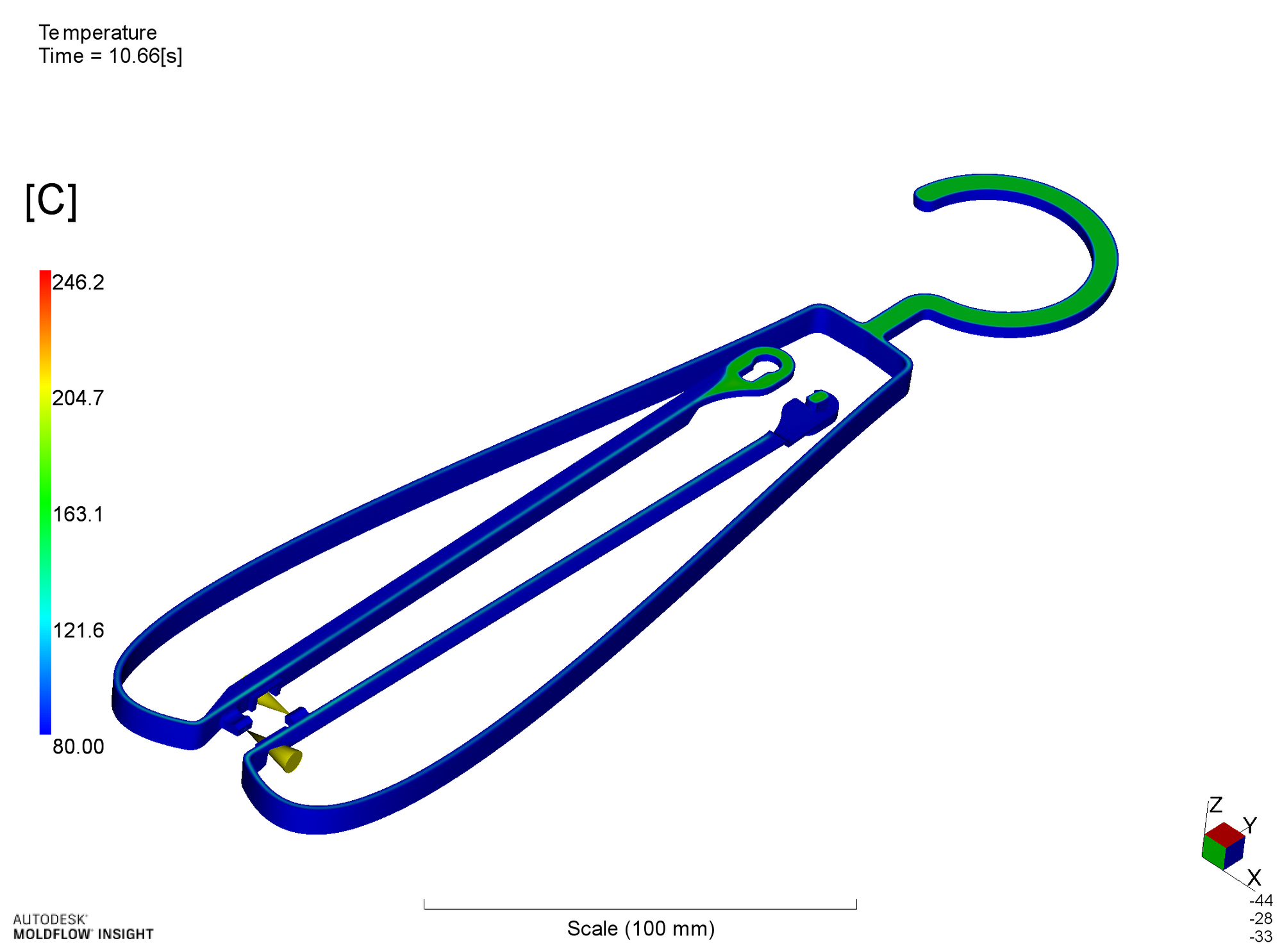
z方向中央断面におけるプラスチックの温度分布を示します。図は離型可能となった時間、充填開始から約11s後の温度分布です。初期形状(離型可能までの時間:約42s)から、全体として厚みを小さくした結果、成形サイクル時間は約11sと大幅に短くできます。
4) ヒケの発生はないか?
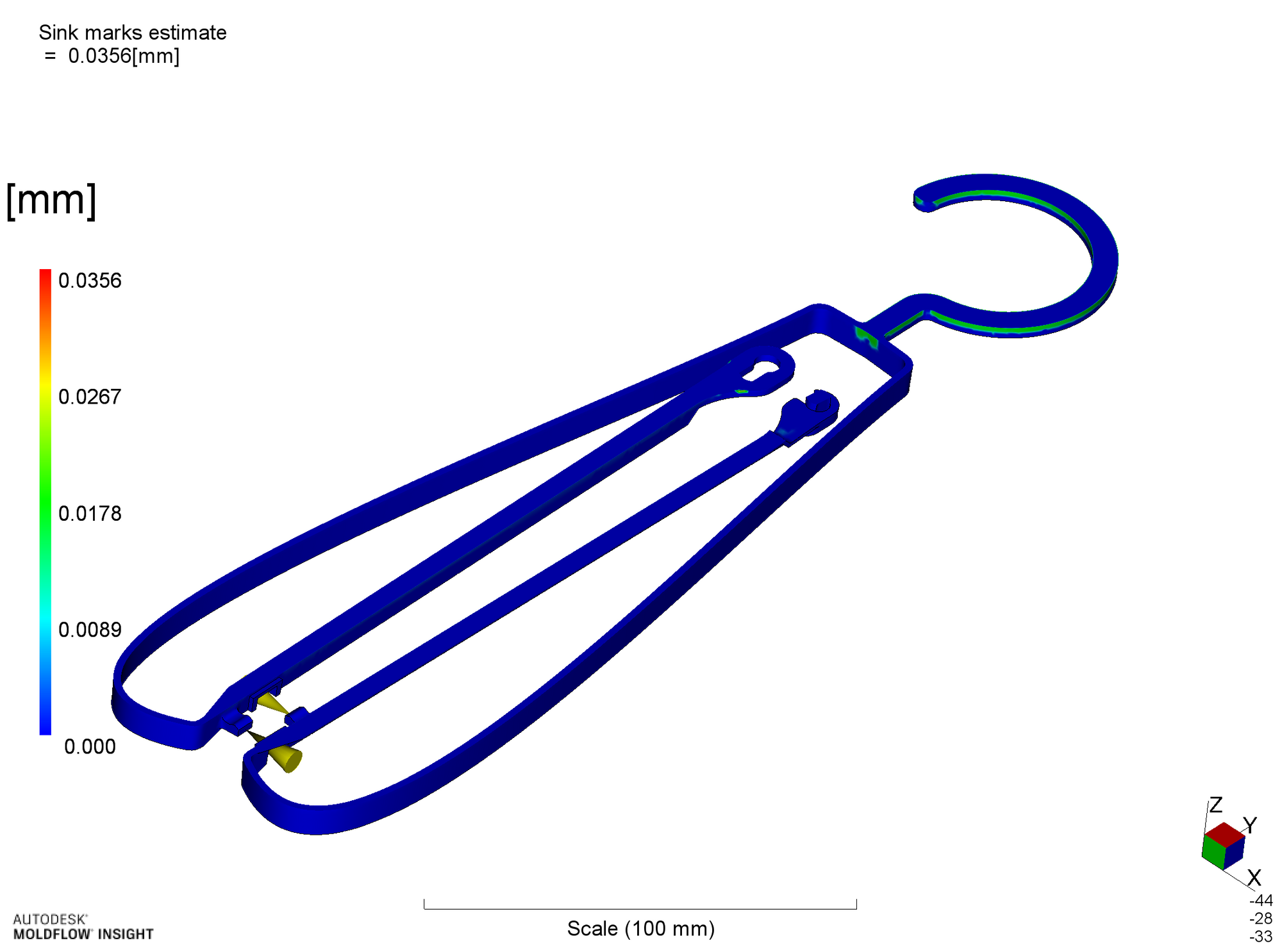
ヒケの発生量を下図に示します。ヒケ(くぼみ)は最大で0.04mm程度と大きくはありませんが、特に光沢のある表面ではヒケが目立つ可能性はあります。また、後に検討する直線部の反り変形対策としてのT字部リブの厚みが大きくなる場合、直線部にもヒケ発生の可能性があります。この計算結果では直線部にはヒケ発生が予測されていません。
基本的には、本商品の機能上ヒケは大きな問題(外観不良)になることはありません。もし必要であれば(ヒケが気になるようであれば)、表面にシボ加工をすることで光沢をなくし、ヒケを目立たなくすることもできます。
5) 反り変形は過大ではないか?
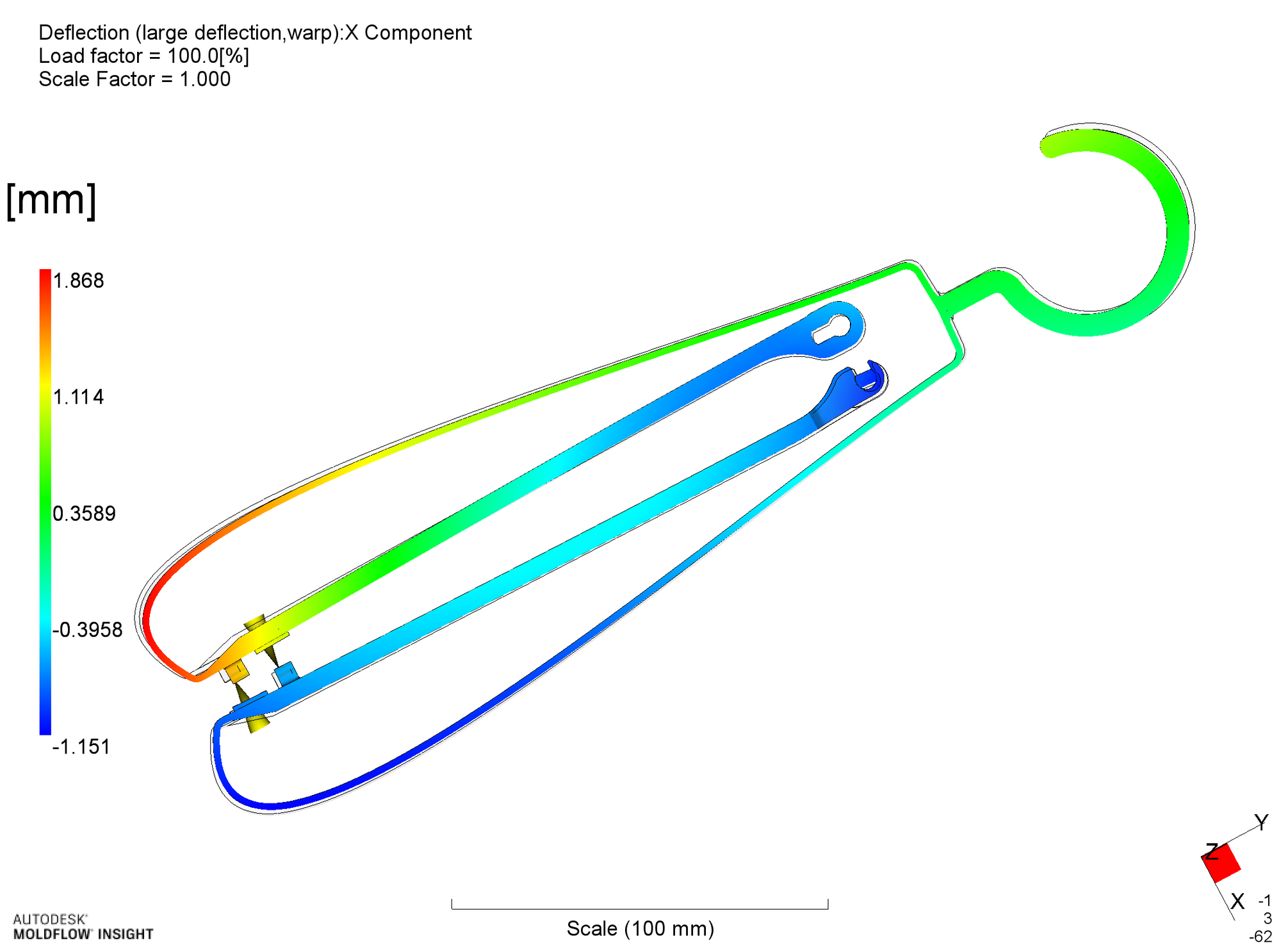
以下にx、y および z方向の反り変形量を示します。
x方向の変形では、弓部での変形が直線部との境界近傍で大きな変形として表れていることがわかります。弓部については、この程度(1.5mm)の変形は問題ではありませんが、直線部の変形(曲がり)については、ハンガー組立時に直線部に圧縮力が作用することから、過度な曲がりは無視できません。
次ステップにて、この直線部の変形について、リブ厚みとの関係を確認し、適正なリブ厚みを決めることにします。
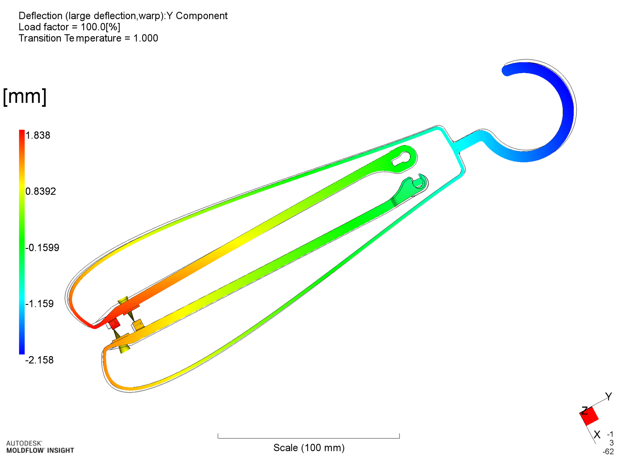
y方向の変形量からは成形収縮による寸法の変化を見ることができます。特に直線部については寸法の設計からの違いについて、機能としての確認をしておく必要があります。
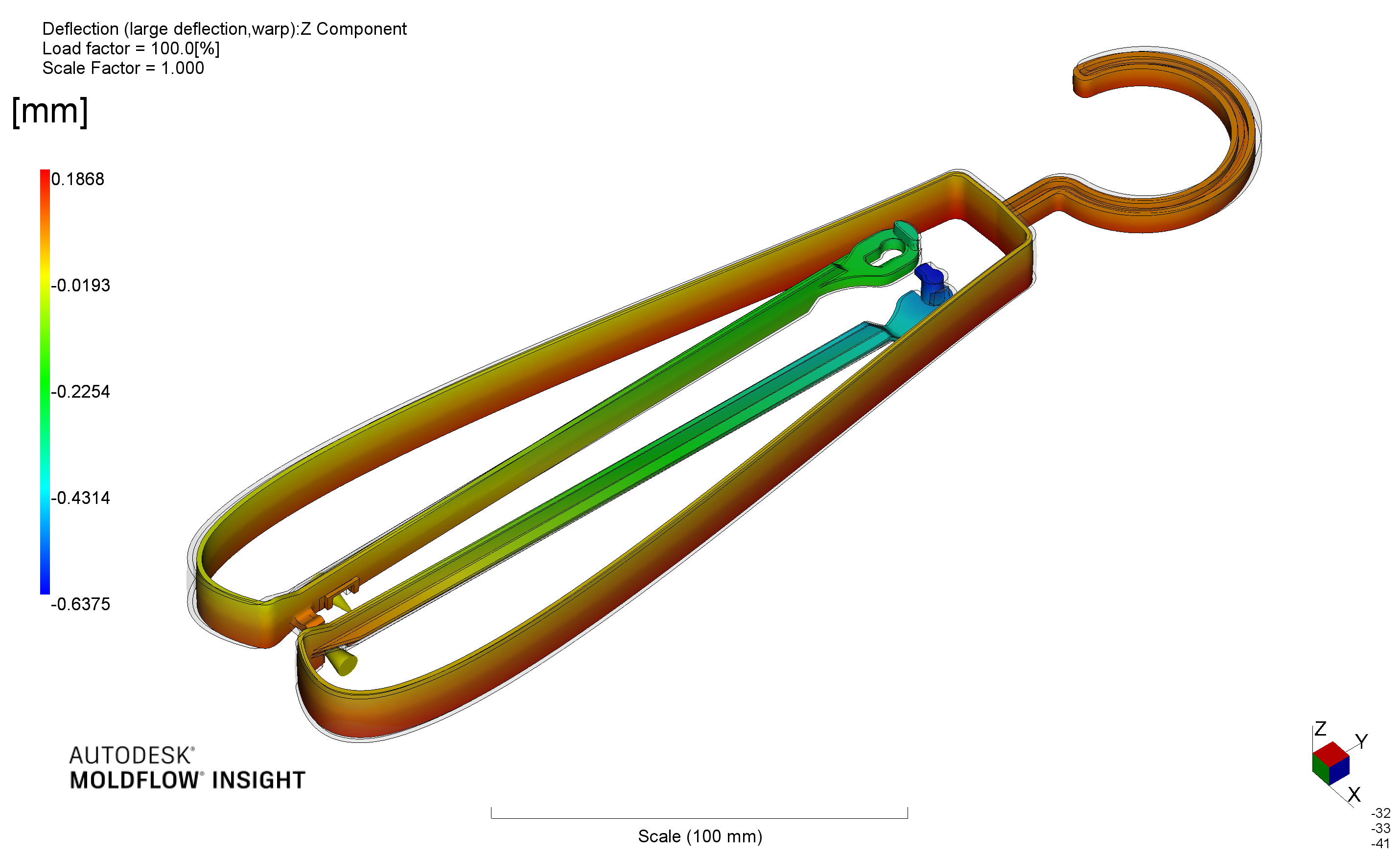
z方向の反りはxy平面外の変形を示しています。計算結果は0.2mm程度であり、問題とはなりません。実際に配置可能な冷却管によっては、不均一な冷却のために反りが大きくなる可能性は残っています。適正な冷却管により反りを低減させることができます。本報では、冷却システムの設計については言及しません。
反り変形を最小にする
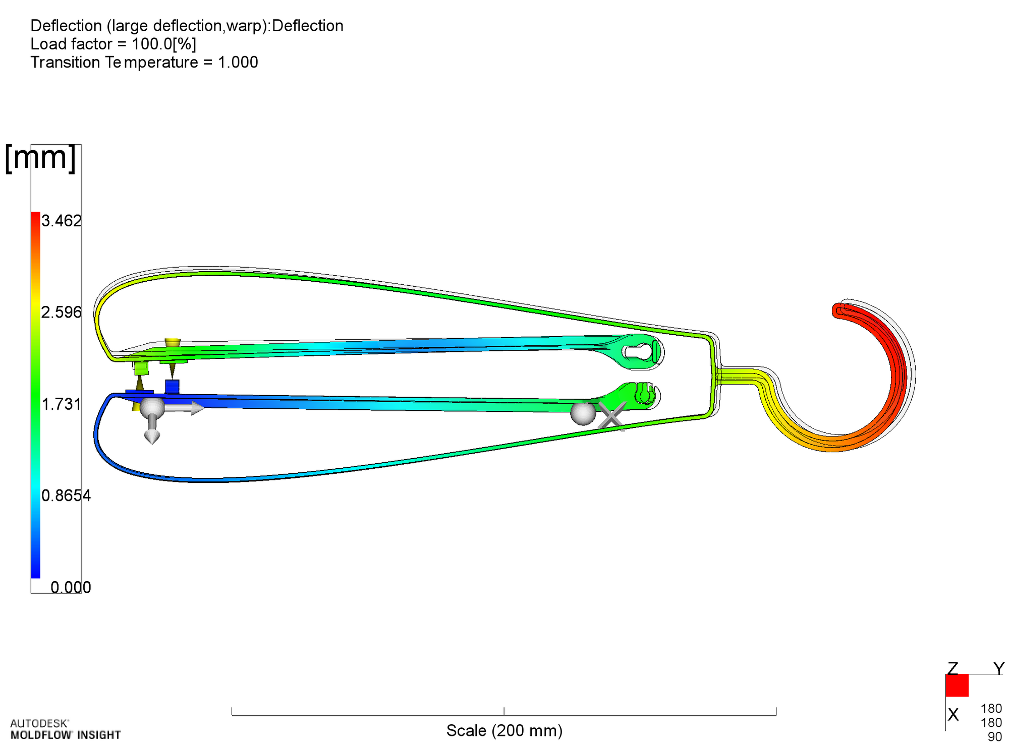
直線部におけるリブの厚み(初期値は1mm)を、1.2, 1.4, 1.6, 1.8, 2.0mmと変化させて、直線部の曲がり量を確認します。ここでは、弓部を含む全体としての変形ではなく、直線部の曲がりのみを確認します。そのために図に例示するように、直線部の一端をピン固定(x,y,z方向の変形を固定、回転は自由)、他端についてはx方向と回転を自由として中央部のx方向変位を求めます。ここで図の下方向がx方向の正なので、下方向に凸に曲がった場合、変形量は正の値となります。この測定方法は、2つの直線部ともに同じなので、同じ形状であれば両者の変形量はプラスマイナスが逆に表されることになります。
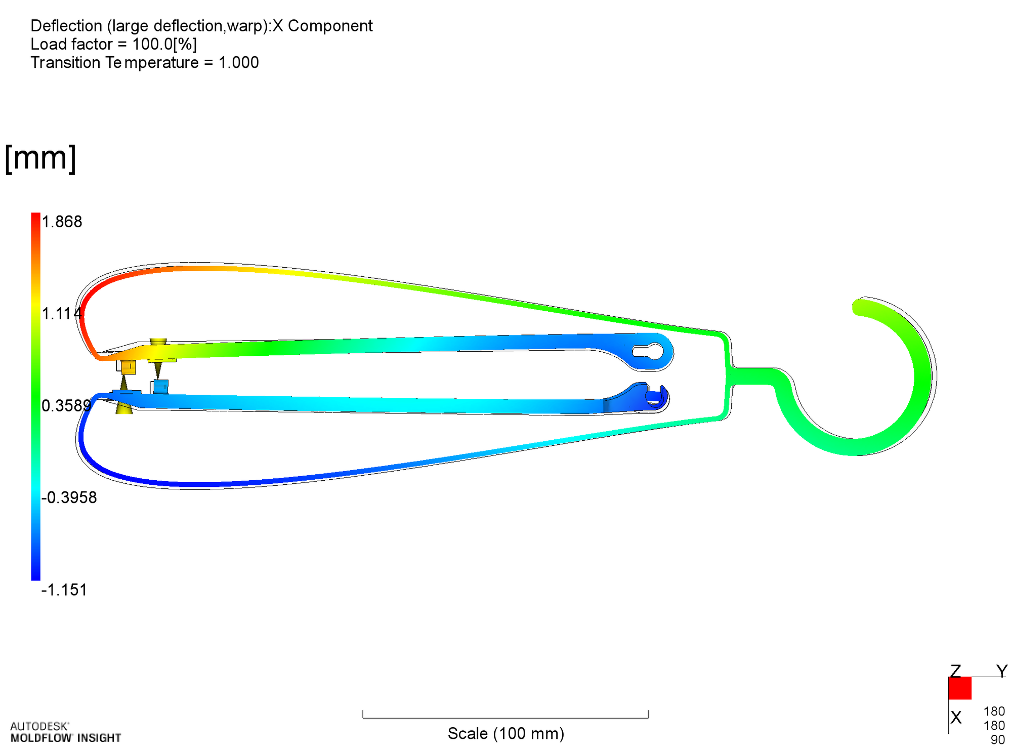
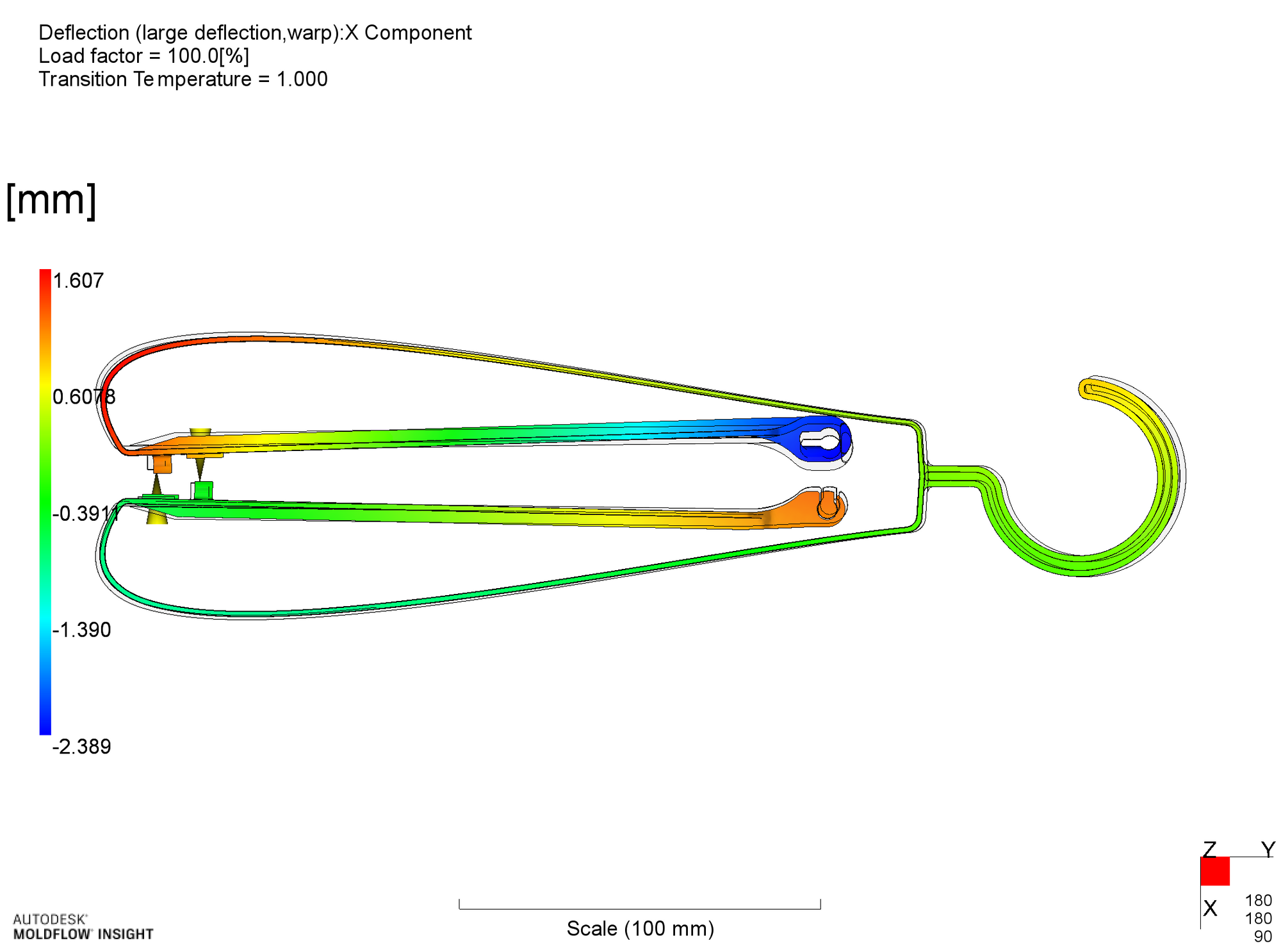
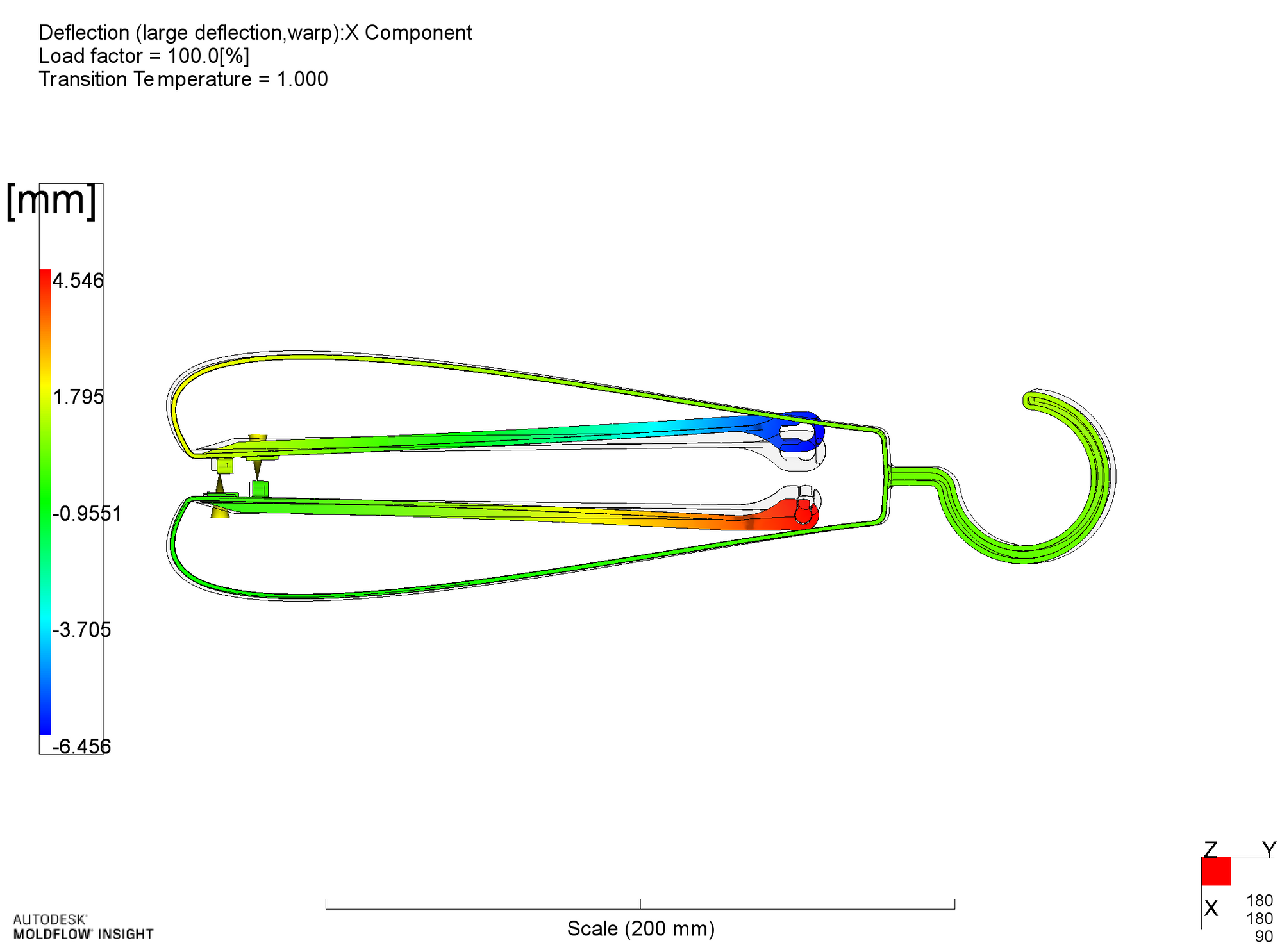
リブの厚みと直線部の変形の関係を確認します。そのために、リブ厚みを \(h_r\) = 1.0, 1.6, 2.0 と変えて、Moldflowによる計算を行いました。結果を以下に示します。
大きな変形では直線部先端が弓部に突き刺さって見えますが、本計算では接触を考慮していないためです。実際には弓部内側表面に接触するので、それ以上は変形は大きくなりませんが、拘束を受け応力として残存し、商品機能への影響は少なからずあります。
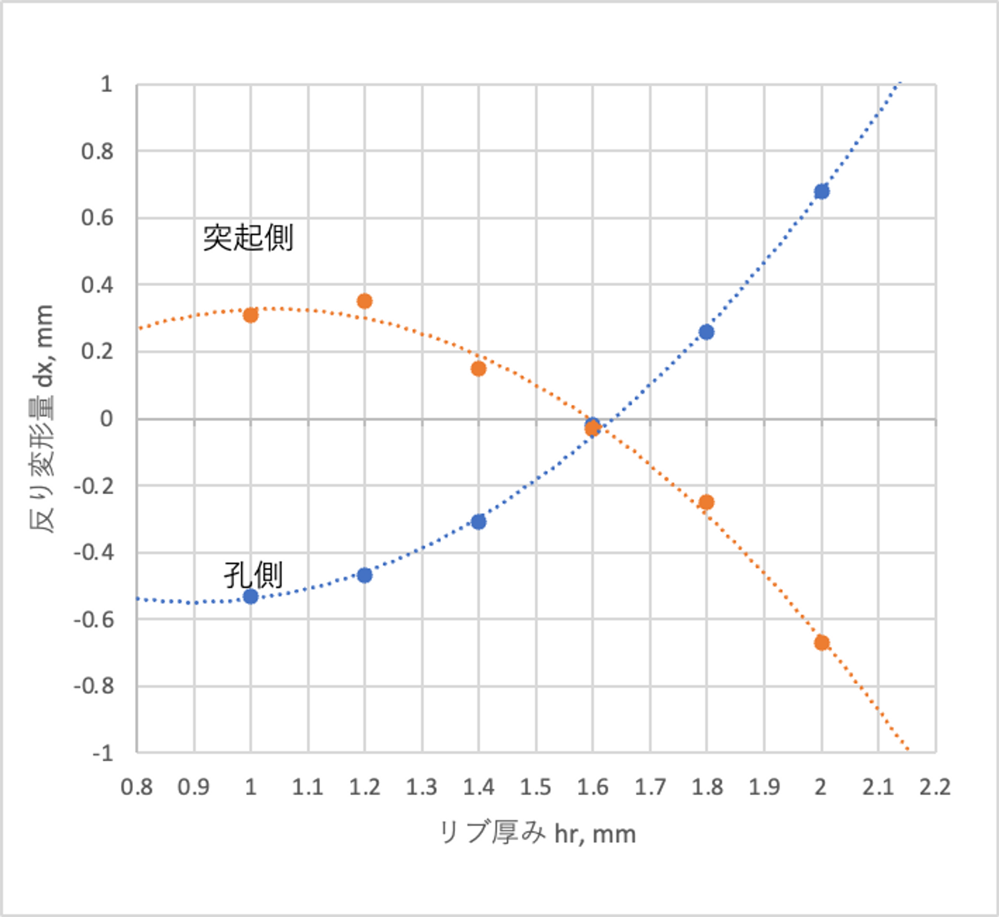
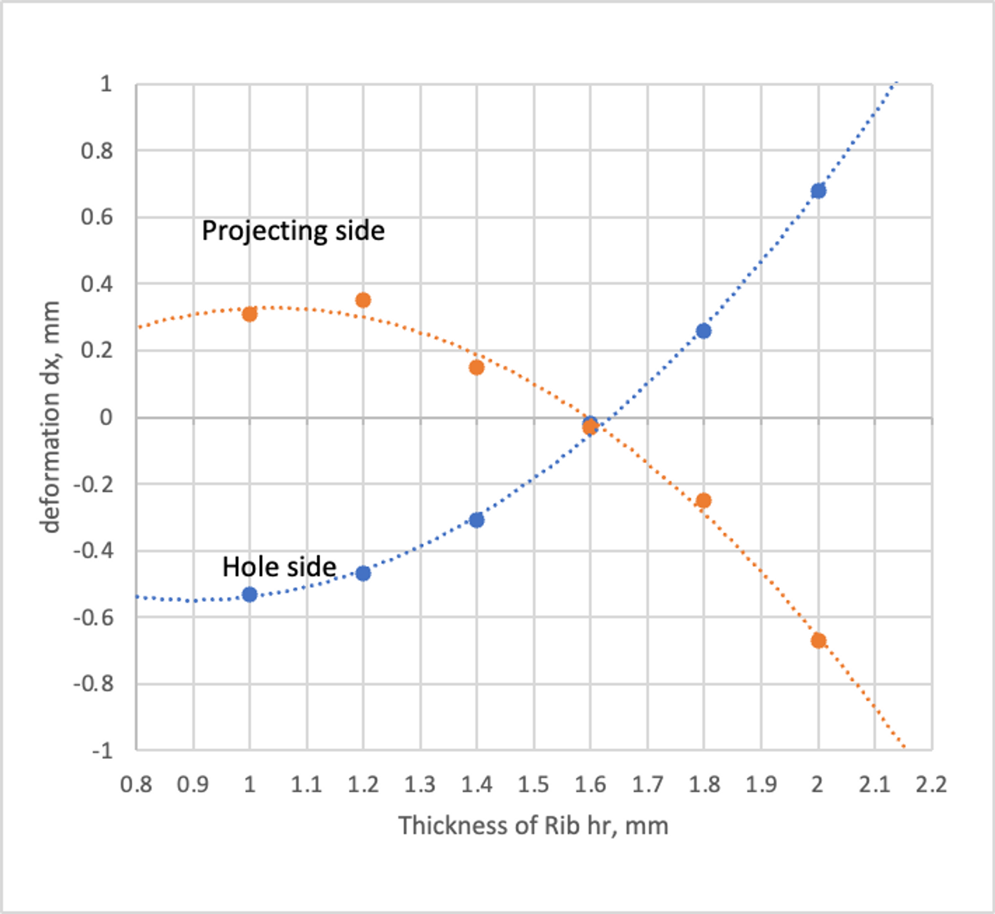
以上の結果から、リブ厚み\(h_r\)との直線部の変形(曲がり)の関係を次のグラフに示します。
これより、\(h_r\)=1.6mmで、変形は最小となります。
再確認
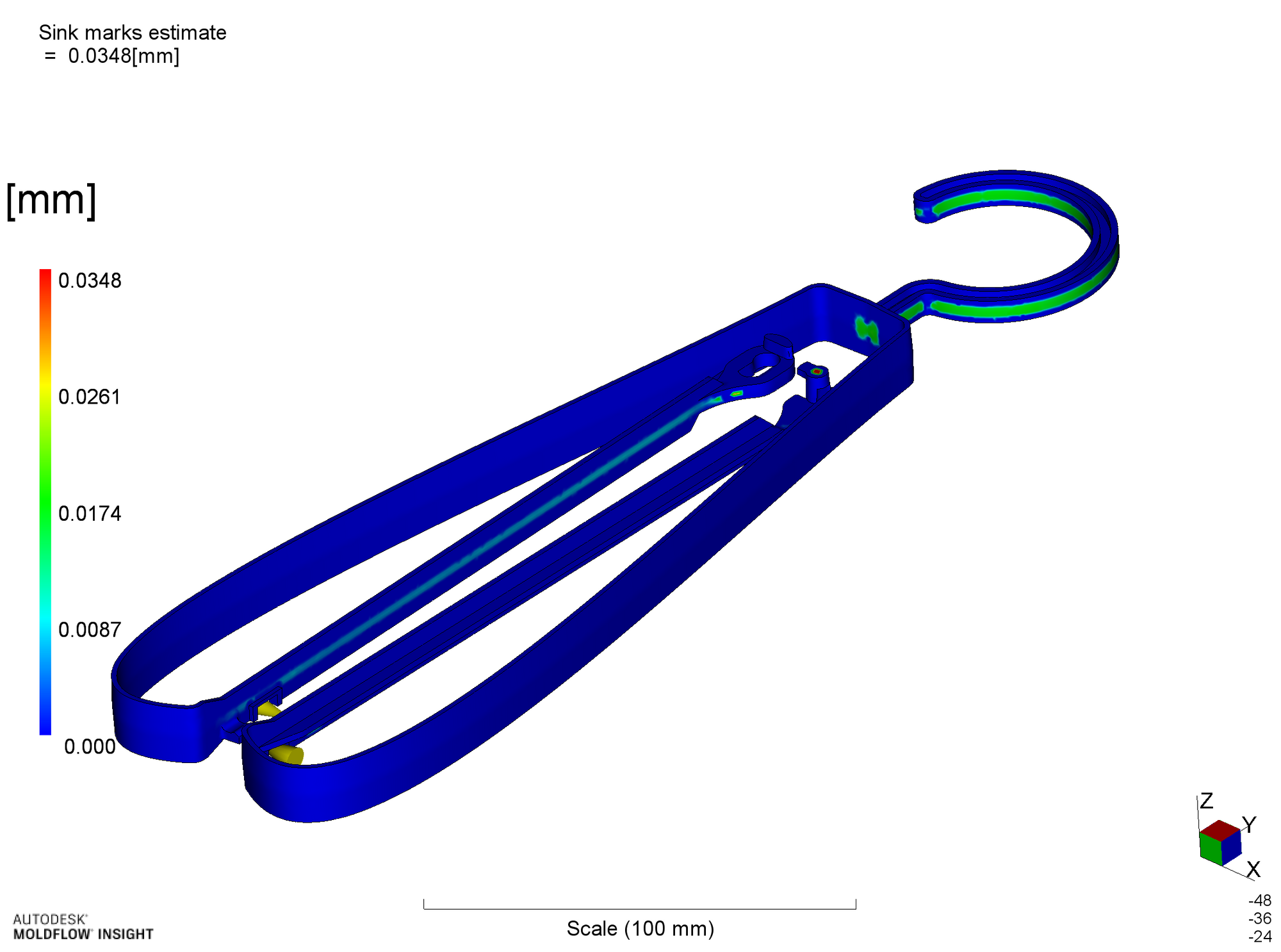
前節のように、直線部の変形を最小にするには、T字部のリブ厚みを1.6mmにすればよいことがわかりました。この寸法でのヒケを確認しておきます。
\(h_r\) = 1.0mmの場合に比べて1.6mmでは、ヒケは大きくなっていることがわかります。しかしながら、ヒケの量は0.001mm程度であり、問題にはなりません。
まとめ
第1部で解説した新しい構造、機能を有する「折りたたみハンガー」ついて、既存の量産工法であるプラスチック射出成形で実現することを目指して検討しました。それに必要な検討項目について理論式やシミュレーションツールを用いて確認を行いました。
本報で金型設計要件については未検討で。溶融プラスチックの流動と冷却に伴い発生する成形不良現象を予測し、それを小さくするための形状設計として展開しました。これにより、量産可能な商品形状を決定することができました。
ここでは折りたたみ可能ハンガーの複数部品の一体化、またはコンパクト化によるコスト低減効果を示していません。これは次報にて解説する予定です。
Introduction
Nature Architects develops product design algorithms that utilize metamaterials. Our goal is to make these products realistically mass producible in terms of delivery, cost, and quality.
This paper describes how to proceed with production design, using the "Folding Hanger" described in Part 1 as a case study. In this product, we proposed a new structure and function by applying a compliant mechanism. We proceeded with the production design concurrently with the functional design described in Part 1.
In Part 2, we present the basic procedure for designing the proposed functionality to be realized with existing mass production technology, in this case plastic injection molding.
Note: In this report, "production design" refers to the study of mold structure, molding processability, cost, and other factors to enable mass production.
Materials, conditions, and terms
Analysis Tools
- Moldflow Insight 2023.
In this report, it is called “Moldflow”.
Material
- POM、Duracon M90-44(Polyplatics)
- Thermal Conductivity \(k\) : 0.24 \(W/mK\)
- Specific Heat \(c_p\) : 2,000 \(J/kg K\)
- Density \(\rho\) : 1,300 \(kg/m^3\) (Melt)
- Mold releasable temperature \(T_e\) : 143 \(^\circ C\)
Molding Condition
- Melt Temperature \(T_i\) : 200 \(℃\)
- Mold Temperature \(T_d\) : 80 \(℃\)
- Flow Rate \(Q\) : 50 \(cm^3/s\)
- Filling Time \(t_f\) : 1\(s\)
- Switching position from speed control to pressure control : Automatic calculation(Moldflow)
- Holding Pressure \(P_h\) : 80% of filling pressure
- Holding Time \(t_h\) : 10s
- Cooling Time \(t_c\) : Automatic calculation (Moldflow)
Injection Molding Machine
- Maximum Injection Pressure \(P_{max}\) : 180 \(MPa\)
- Maximum Clamping Force \(F_{max}\) : 7,000 \(ton\)
Brief review of practicality
Injection molding will be used as a practical mass production method. The first step is to examine the feasibility of the process while keeping cost in mind. This stage is a rough confirmation of the following three items. After this stage, a detailed examination is conducted with a modified design.
- Can the molten plastic be filled into the mold?
- Are thicknesses of the product appropriate?
- Can the product be removed from the mold?
The initial shape and dimensions of the foldable structure described in Part 1 are shown in the figure below.
-
Can the molten plastic be filled into the mold?
-
Is the shape too thin for the overall size of the part, i.e., the typical flow length?
The minimum thickness is 2.2 mm for a flow length of approximately 400 mm (depending on the gate position), which is not extremely thin. Therefore, it can be judged that it can be filled with molten plastic in the injection molding process. On the other hand, the maximum thickness is 6 mm, which is sufficient for filling, and the thickness can be further reduced.
-
-
Are thicknesses of the product appropriate?
- Is the molding process time too long?
-
Can the thickness be reduced?
It is estimated that the "cooling time" in the injection molding process will be longer due to the thicker 6mm at the hook. It is necessary to consider reducing the thickness.
From the unsteady heat conduction in a flat plate, the cooling time is expressed by the following equation.(Ref.:Rao,Natti S.: Design Formulas for Plastics Engineers, Hanser, Munich(1991) p.50 )
\(t_c = \frac{1}{\alpha} \Bigl(\frac{h}{\pi}\Bigr)^2 \space ln \Bigl[ \frac{4}{\pi} \space \frac{T_d - T_i}{T_d - T_e} \Bigr]\)where, \(t_c\) : cooling time, \(h\) : thickness of the plate, \(T_d\) : mold temperature, \(T_i\) : melt temperature, \(T_e\) : ejection temperature, and the thermal diffusivity \(\alpha\) in this equation is defined as
\(\alpha = \frac{k}{\rho \space c_p}\)where, \(k\) : thermal conductivity, \(\rho\) : density, \(c_p\) : specific heat.
The cooling time is determined from the physical properties and molding conditions described at the beginning of this report. For the hook section with a maximum thickness of \(h\) = 6mm, the cooling time \(t_c\) = 35s is predicted to be the time required for the hook section to be ready for removal (”ejection” in injection molding).
Assuming that the filling time \(t_f\) = 1s, holding time \(t_h\) = 10s, and mold opening to mold closing time \(t_k\) = 10s, the molding cycle time is the sum of the above and is predicted to be approximately 56s.
Note : Regarding the cycle time prediction.
Strictly speaking, cooling of the molten high-temperature plastic begins when it contacts the mold wall at the start of filling. Since heat input is more dominant than cooling during the filling process, it is practical to assume that cooling begins during the pressure holding process after filling is complete. The purpose of the pressure holding process is to replenish the molten plastic that is shrinking due to cooling, i.e., the heat inflow continues. Although the pressure holding time \(t_h\)=10s is assumed, this is a machine-controlled setting in the molding machine, and the heat inflow may stop in the middle of the pressure holding time. Therefore, the actual cooling time can be considered to include the pressure holding time.
However, this formula does not take heat input into account, and the time required for cooling cannot be strictly estimated. In other words, the molding cycle time that can be estimated with the above theoretical formula is in the range of 46 to 56 s, and it should be recognized that there are variations. If half of the pressure holding time is adopted, the cycle time can be estimated to be about 51s. However, we would like to estimate conservatively in the initial study.
The so-called "dry cycle \(t_k\) from mold opening to mold closing can also be increased by setting equipment and devices, but is estimated conservatively as well.
The following are the results of the Moldflow calculations, which are more realistic because it calculate heat input and cooling in series. The time required for sufficient cooling to allow mold release can be predicted as follows
\(t_f + t_h + t_c\) = 42s
From this, the molding cycle time can be predicted to be around 52s.
The figure below shows the temperature distribution (cross-section in the center of the z-direction) during the mold release time. It can be seen that the temperature of the hook section, which has a large thickness, is high, i.e., it takes a lot of time for cooling. Conversely, the cycle time can be shortened by reducing the thickness of this section.
Note: Both the theoretical formula above and the Moldflow calculation assume that mold release is possible when all temperatures in the thickness direction reach \(T_e\) (100% solidification). In reality, however, there are cases where mold release is possible even if, for example, the plastic inside the mold is in a molten state at high temperatures, and it is important to promote mold design that allows mold release without molding defects even if the mold is not 100% solidified. Specifically, if the ejector pins are properly positioned, the mold can be removed without applying excessive force during removal and without deforming the part.
However, it should be noticed that changing the demolding time will cause differences in the cooling conditions within the part. Especially with crystalline plastics, the degree of crystallinity changes, resulting in a change in the shrinkage rate. Shrinkage changes affect the dimensions and warpage of the molded product, which may result in molding defects that were not anticipated at the time of product design. To eliminate rework, we believe it is important to proceed simultaneously with functional and production design of the product.
Based on the functions required for this product (see Part 1), a certain degree of rigidity is necessary for straight sections and hook sections. Therefore, instead of simply reducing the thickness to shorten the cycle time, it is necessary to design the product to have, for example, an H-shaped cross-sectional shape. This will shorten the cooling time and at the same time ensure constant rigidity.
-
Can the product be removed from the mold?
- Are there any shapes that are undercut?
-
Is there a draft angle?
The plane in which the part (hanger) is placed on the floor is the xy-plane. The part is placed so that the mold is opened in the z direction for removal (mold release). The parting plane (PL: parting line) of this part is the xy-plane, the center of the z-direction (z=0). z-direction is the direction of extraction, and the first requirement is that there be no "undercut" shape in order to release the part. Even if there is an undercut, it is possible to make the mold releasable by providing a slide core in the mold, but the mold will be expensive, so we want to design a shape with as few undercuts as possible.
From the initial study stage of this part, it has already been designed without undercuts.In addition, it is essential to provide an appropriate "draft angle" to prevent molding defects during mold release. Generally, the draft should be 0.5 to 1 degree or more. The initial design does not provide a draft angle, so the design must be changed.
Additional Information: In injection molding, the molded product must remain on the moving side of the mold (where ejector pins are positioned in this side when it opens). Since this product is symmetrical in the +z and -z directions, if the same mold release resistance is used, specifically if the same draft angle is used, the molded product cannot be reliably remain on the moving side. To avoid this instability, this can be achieved, for example, by making the draft angle on the fixed side larger than that on the moving side.
However, this would break the symmetry in the z-direction. As a function of this product, it is necessary to check the degree of influence of asymmetry. This report does not examine about this.
Design proposal considering injection molding
The proposed design, which takes into account the requirements described in the previous section, is shown in the figure below.
The hook section is H-shaped, and the straight section is T-shaped to reduce the thickness and ensure the necessary rigidity.
Some cross-sectional dimensions of the proposed design are shown in the figure below.
The draft is set at the top and bottom from the center in the z-direction.The thickness of the T-section ribs (the part protruding horizontally in the figure) is a variable to minimize warp deformation in the injection molding process described below, but the initial value is 1 mm. Preliminary studies have confirmed that the design intent can be satisfied even if the rib thickness is varied between 1 and 2 mm.
Evaluation of molding processability
Now we have determined a shape that is feasible for injection molding. Next, we proceed to check for molding defects using Moldflow.
Simplification: Here, runners are not placed, but only the filling of the molten plastic from gates is evaluated. That is, if multiple gates are provided, we assume that the molten plastic is filled simultaneously and evenly distributed through them. This is expected to ensure proper runner balance in the next step of mold design. Similarly, mold cooling circuits are not placed at this stage. In other words, it is assumed that the molten plastic is cooled uniformly from the mold walls it contacts. In reality, it is expected that the parts that make up the inside of the hanger will be relatively difficult to cool. This study is based on the expectation that the layout of cooling circuits will provide as much uniform cooling as possible in the mold design. In reality, there are some areas where cooling circuits cannot be placed, and it can be predicted that non-uniform cooling will result in large warpage deformation. Therefore, we will proceed with the study with the understanding that there will be some rework in the design, such as shape modifications.
In the following, we will review the calculation results, assuming the phenomenon of molding defects.
The figure below shows the mesh used in the calculation (only the surface is shown).The two positions indicated by the cone in the lower left part of the figure are used as gates.
In fact, by placing two gates in the bow section, simultaneous filling of three final filling positions (flow ends) can be achieved.However, the two gates were chosen because this bow section is thin-walled and the filling and holding pressure for the straight section should be sufficient (thereby reducing shrinkage of the straight section).
1) Do unfilled defects (short shots) occur?
Simultaneous filling of the three filling ends has not been achieved. However, there were no unfilled defects, partly because the injection rate was set at a relatively high 50\(cm^3/s\).
The temperature distribution of the molten plastic at the flow front (the leading edge of the flow during filling) is shown below. If the temperature drops significantly during the filling process, it will solidify and become unfilled, but in this case, no temperature drop is observed. On the contrary, the high viscosity of the fluid causes shear heating, resulting in a temperature higher than the inflow temperature of 200°C.
2) Are there any weld lines that reduce strength?
The location of weld lines is shown in the figure below.
Weld lines are expected to occur at both ends of straight sections. Especially on the hole side (left side of the figure), a meeting of flows that bypasses the part forming the hole will occur. Since this is the filling end, suppression of weld line strength reduction due to velocity change (see below) cannot be expected for this area.
As a product function, the force that pulls this hole toward the end does not act on this hole, so it is expected that there will be no problem even if there is strength reduction. However, since strength reduction at the weld line cannot be predicted quantitatively in general, it is necessary to actually make and test the weld line, and if the strength reduction is not negligible, then some design change are necessary.
This report does not go so far as to mention this.
The flows from the left and right bows meet near the base of the hook. This is predicted to be the location where the weld line occurs, but this is not the end of the flow, and the flow to the hook section continues after the meeting. At the collision area, back-flow from right to left in the figure also occurs, and further flow continues, causing polymer entanglement, especially in the inner layer. This is expected to keep the strength of this area from decreasing significantly. For confirmation, changes in flow velocity are shown below.
3) Is the cooling time adequate?
Shows the temperature distribution of the plastic in the central cross-section in the z-direction. The figure shows the temperature distribution after about 11 s from the start of filling, the time when mold release is possible. As a result of reducing the overall thickness from the initial shape (time until mold release: approx. 42 s), the molding cycle time can be significantly shortened to approx. 11 s.
4) Are there any sink marks?
The amount of sink marks is shown in the figure below. Although these sink marks (dimples) are not large, 0.04 mm at the maximum, they may be noticeable.
In addition, if the thickness of the ribs in the T-section is large enough to prevent warp deformation of the straight section, which will be discussed later, there is a possibility that sink marks may also occur in the straight section. This calculation result does not predict the occurrence of sink marks on the straight sections.
Basically, sink marks are not a major problem (appearance defect) for the function of this product. If necessary (if sink marks are a concern), the surface can be treated with a grainy finish to reduce the luster and make sink marks less noticeable.
5) Is warpage excessive?
The warpage in the x, y and z directions are shown below.
In the x-direction deformation, it can be seen that the deformation at the bow section is expressed as a large deformation near the boundary with the straight section. This level of deformation (1.5 mm) is not a problem for the bow section, but excessive bending of the straight section cannot be ignored because of the compressive force acting on the straight section during hanger assembly.
In the next step, we will check the relationship between the rib thickness and the deformation of the straight section to determine the appropriate rib thickness.
From the deformation in the y-direction, we can see the change in dimensions due to molding shrinkage. Especially for straight sections, it is necessary to check as a function of the difference from the design of the dimensions.
Warpage in the z-direction indicates deformation outside the xy-plane. The calculated result is about 0.2 mm, which is not a problem.
Although not only in the z-direction, there is still a possibility that warpage may increase due to non-uniform cooling, depending on the cooling channels that can actually be placed. Warpage can be reduced by appropriate cooling channels. The design of the cooling system is not discussed in this report.
Minimize warpage
The thickness of the ribs in the straight section (default value is 1 mm) is varied from 1.2, 1.4, 1.6, 1.8, and 2.0 mm to check the amount of bending in the straight section. Here, only the bending of the straight section is checked, not the deformation of the whole including the bow section. As shown in the figure, one end of the straight section is pinned (fixed deformation in x, y, and z directions, free rotation), and the other end is free in x direction and rotation, to obtain the displacement in x direction of the center section. Since the downward direction in the figure is positive in the x-direction, the amount of deformation is positive if the bend is convex in the downward direction. Since this measurement method is the same for the two straight sections, if they have the same shape, the amount of deformation for both will be expressed as the opposite of positve and negative.
Check the relationship between rib thickness and deformation of straight sections. To do so, we performed Moldflow calculations with rib thicknesses of \(h_r\) = 1.0, 1.6, and 2.0.
The results are shown below.
Note that the end of the straight section appears to stick into the bow in the large deformation, but this is because this calculation does not take contact into account.
In reality, the deformation does not grow any larger because of the contact with the inner surface of the bow, but it remains as a stress due to the restraint and has no small effect on the function of the product.
Based on the above results, the following graph shows the relationship between the rib thickness \(h_r\) and the deformation (bending) of the straight section.
It shows that the deformation is minimum at \(h_r\)=1.6mm.
Revalidation
As in the previous section, we found that to minimize the deformation of the straight section, the rib thickness of the T-section should be 1.6 mm. We will check the sinkage at this dimension.
We see that the sinkage is larger at \(h_r\)=1.6 mm than at \(h_r\)=1.0mm. However, the amount of sink marks is only about 0.001 mm and can be ignored.
Conclusion
We studied the "folding hanger" with a new structure and functions described in Part 1, aiming to realize it by plastic injection molding, which is an existing mass production method.
The necessary design items were studied using theoretical formulas and simulation tools.
Although the mold design requirements have not yet been examined in this report, we predicted the molding defect phenomenon that occurs with the flow and cooling of molten plastic, and developed a shape design to reduce it.
As a result, we were able to determine a product shape that could be mass-produced.
This report does not show the cost reduction effect of integrating multiple parts of a foldable hanger or compacting it. This will be explained in the next report.
