
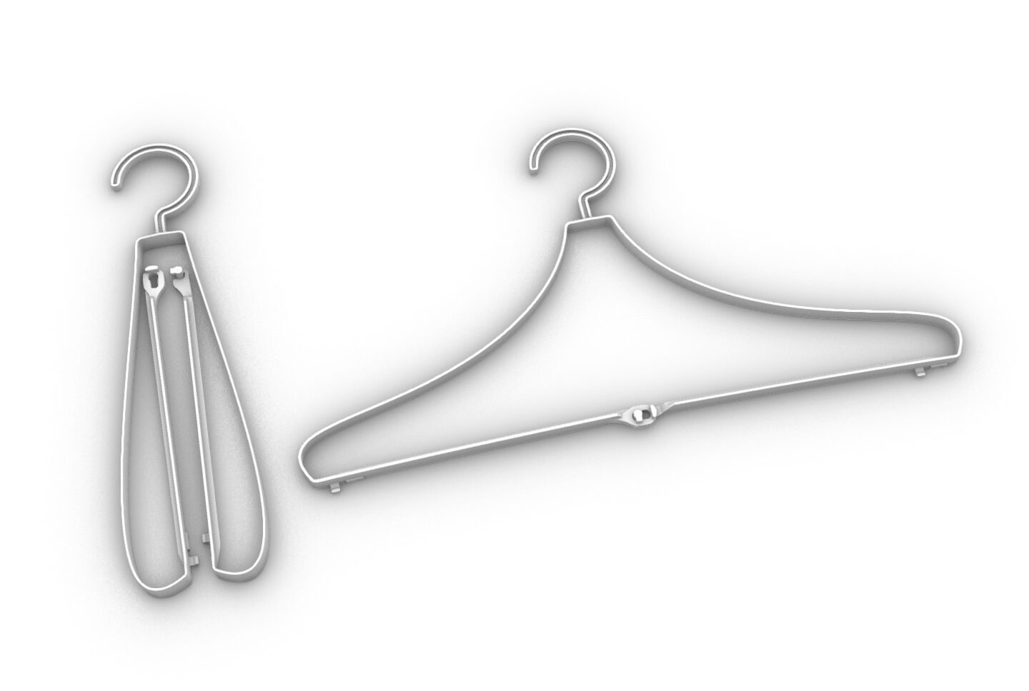
はじめに
弾性変形を活用して力や動きを伝える機構をコンプライアントメカニズム(Compliant Mechanism)と呼びます。バネやプラスチック製品のスナップフィットなどもその一つです。
Nature Architectsでは、コンプライアントメカニズムを用いて複数部品で構成されていた製品を一体化することで、機能性向上や製造コスト低減を実現する設計を行っています。
この記事では「折りたたみハンガー」の設計を題材に、設計の考え方、社内ツールなどについて具体的な設計フローに沿って紹介します。
課題設定
携帯性や収納性を高めるために、折りたたむことができる衣類ハンガーは多数市販されています。通販サイトに掲載されている10製品について確認したところ、写真を見る限り3~10数点の部品の組み立てを必要とする設計となっていました。
本記事ではコンプライアントメカニズムを活用することで以下のような折りたたみハンガーの設計を行います。
設計コンセプト
- 一体成型可能な折りたたみハンガー
- 成形時にコンパクト(金型面積を効率的に利用できる)
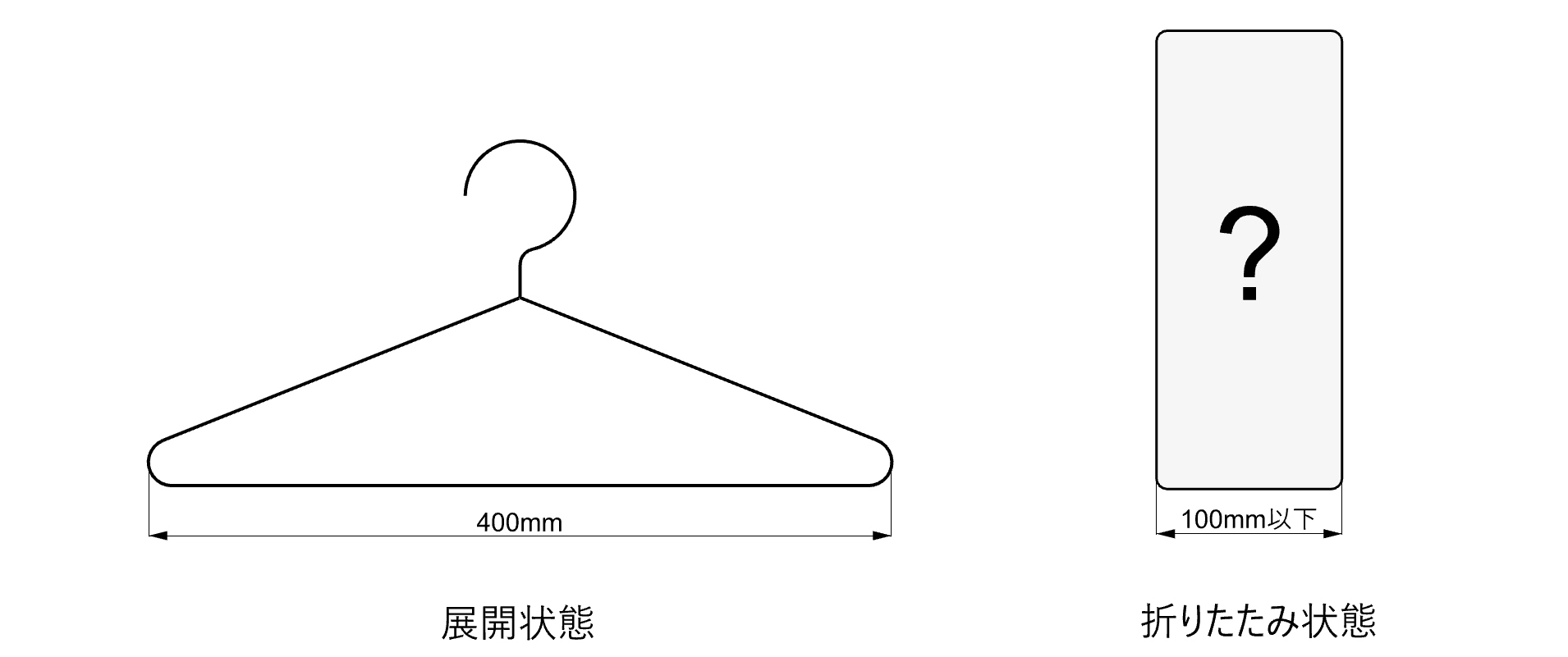
設計する折りたたみハンガーの要件は以下とします。これらの要件は市販されている製品の平均的な寸法などから決定しました。
設計要件
- 広げたときに服をかけられる形状となる
- 展開時横幅:400mm
- 折畳時横幅:100mm以下
- 厚み(図の奥行方向):15mm以下
- 折りたたみ状態 ⇨ 展開状態 遷移荷重:3N±10%
また、製造性を考慮して以下の前提を置きます。
製造制約
- 形状:射出成形で製造可能で、アンダーカットなしの形状とする
- 材質:POM M90-44 (弾性率2500MPa、ポアソン比0.35)
- 許容応力:31MPa(クリープ破壊寿命が10年となる応力)
機構の選択
市販の折りたたみハンガーの変形機構は様々ですが、基本的には変形しない剛体部と、回転自由度をもったヒンジ部分から構成されています。一体化するにあたっては、ヒンジをコンプライアントメカニズムで置き換える必要があります。
コンプライアントメカニズムのヒンジで代表的な形状には以下のような種類があり、必要な自由度や反力・製造制約などによって選択します。これらの機構を複数を組み合わせて使用することもあります。
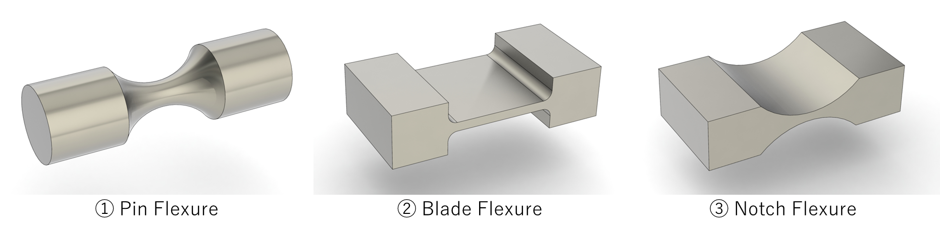
Created by modifying "Pin Flexure", "Blade Flexure" and "Notch Flexure" © 2017 OptoMechEngineer (Licensed under CC BY-SA 4.0)
今回は、平面内の変形が必要で、必要な変形量が大きいことから、Blade Flexureを選定します。純粋にヒンジという機能を置き換えるだけであれば1軸まわり回転自由度のみを有するNotch Flexureのほうが精度に優れていますが、今回は動きの精密さよりも許容応力内での変形量が大きいことを重視し、Blade Flexureを選定しました。
また、このBlade Flexureは、0.2mm~0.4mm程度の薄さに成形しリビングヒンジとしても使用されることがありますが、今回設計する折りたたみハンガーでは、折りたたみ状態から展開状態に遷移する力を3N程度としたいので、より厚く長い寸法とし、全体を弓のようにしならせて使用することにします。
全体構成
ハンガーの構成と、組み立て、開閉操作について下の図に示します。

図中左側の状態で成形したあと、「ヒンジ部」を組み立てることで「折りたたみ状態」となります。その後、ヒンジ部または直線部を手で動かすことで、折りたたみ状態と展開状態を行き来することができるようにします。
「ヒンジ部」は離型後に組み立てることでヒンジとして機能する設計とします。リビングヒンジを採用し一体成型することも考えられますが、図の前後方向の金型分割での成形が困難であることや耐久性の懸念から、今回は組み立て式ヒンジとします。
「弓部」は前述のBlade Flexureを多数連結したものとみなすことができます。ただし曲線的に連結していること、また大変形させることから、同機構が単独で本来持つ自由度の拘束は弱まっています。今回は変形量と反力、広げたときにハンガーの形状になることを重視し、このような使い方としています。
「直線部」は、ヒンジ部と弓部下端との距離を一定に保つ役割があり、ほぼ剛体として機能するよう、十分な曲げ剛性を持たせる必要があります。
独自設計環境
変形後にちょうどハンガーらしい形状になる曲線の梁を設計するにはどうすればよいでしょうか。リビングヒンジのように動きが単純な場合や、微小変形を仮定できる場合は比較的容易です。しかし、今回は梁の広い範囲が大きく変形するため、形状修正と解析結果の確認の多数の反復を必要とし、一般的なCAD+CAE環境では困難です。
弊社では、3DCAD RhinocerosのプラグインであるGrasshopper上で機能する様々な設計環境を独自に開発し、設計問題に応じて柔軟に使い分けています。(Grasshopperについては過去の記事で詳しく紹介しています。)
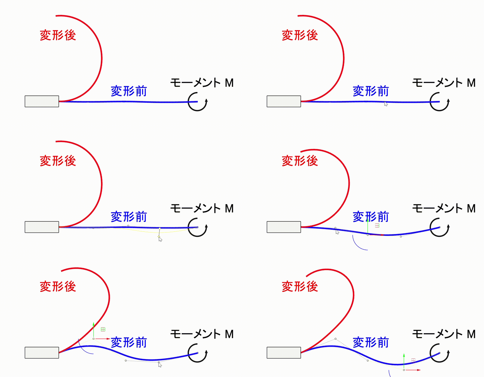
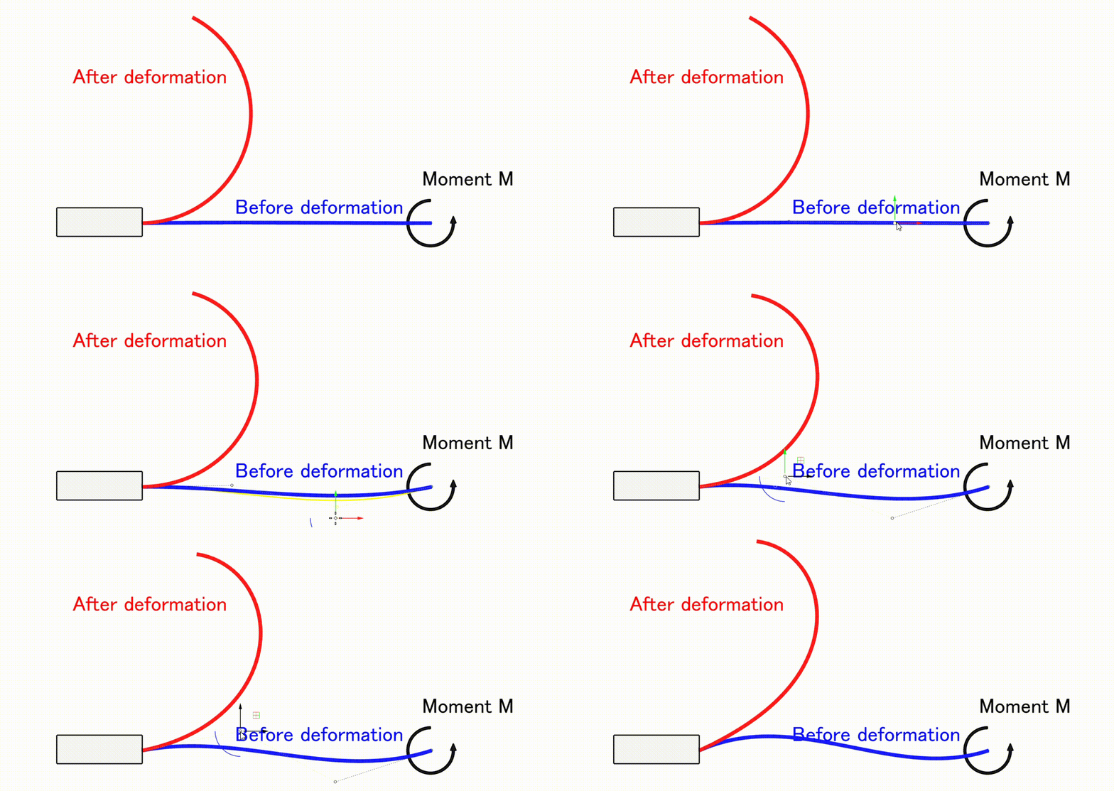
今回は、梁を2次元梁要素でモデル化し変形をリアルタイムで確認しながら設計を行える環境を使用します。この環境を活用することで、多数の形状を短時間で検証することができ、目的の変形をする機構を効率よく探索することができます。
形状検討
上記ツールを活用して、弓部および直線部の形状を具体化していきます。
まず解析の設定をして、成形時の形状をモデリングすれば即座に解析が走り、
- 折りたたみ状態と展開状態の形状
- 変形に要する力
- 途中の最大応力
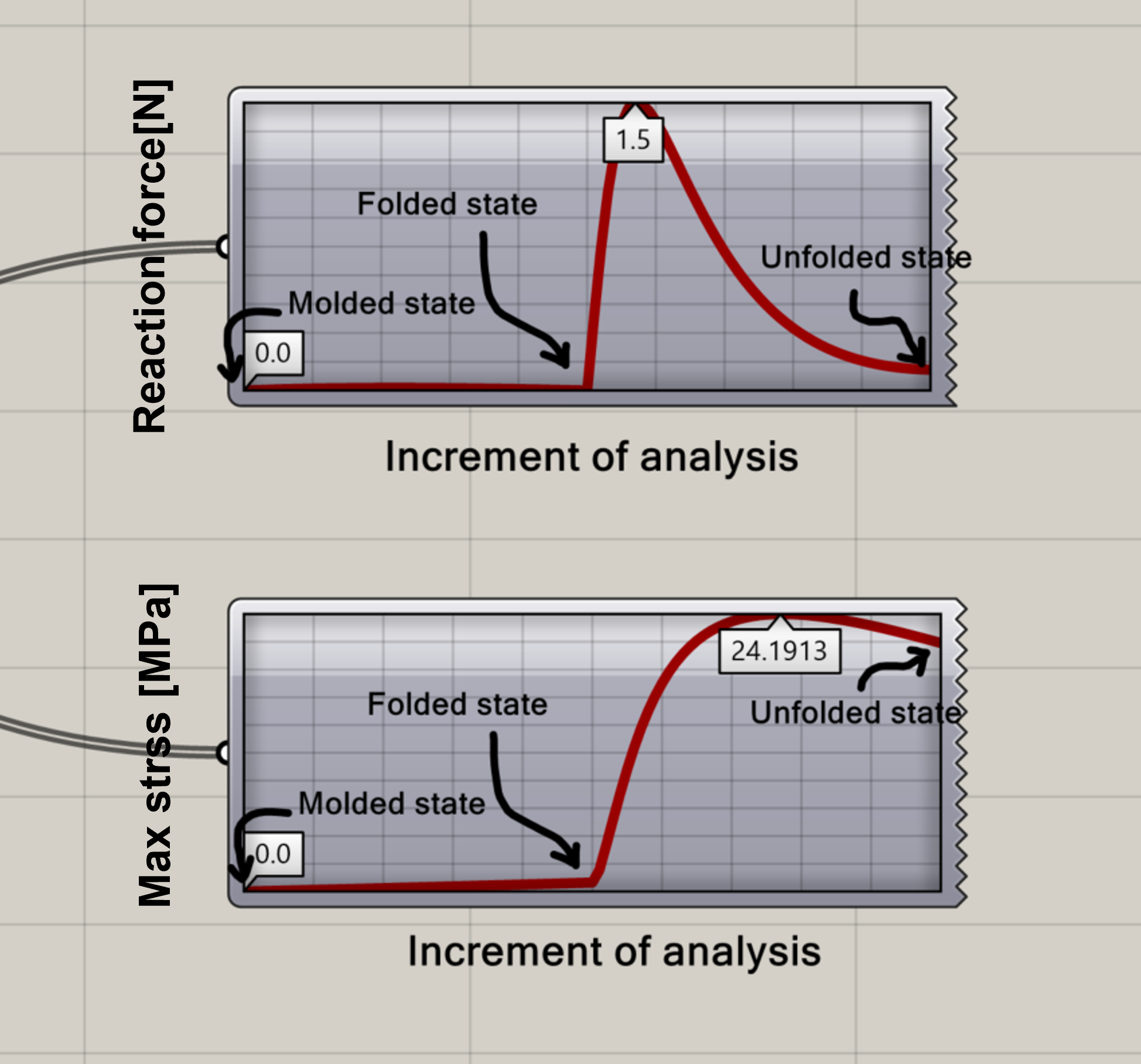
が確認できる状態にします。このときの境界条件は、フック部の付け根を固定とし、ヒンジ部は最初にX方向の変位を与えて組立状態にし、続いてY方向の変位を与えて展開状態まで変形させています。
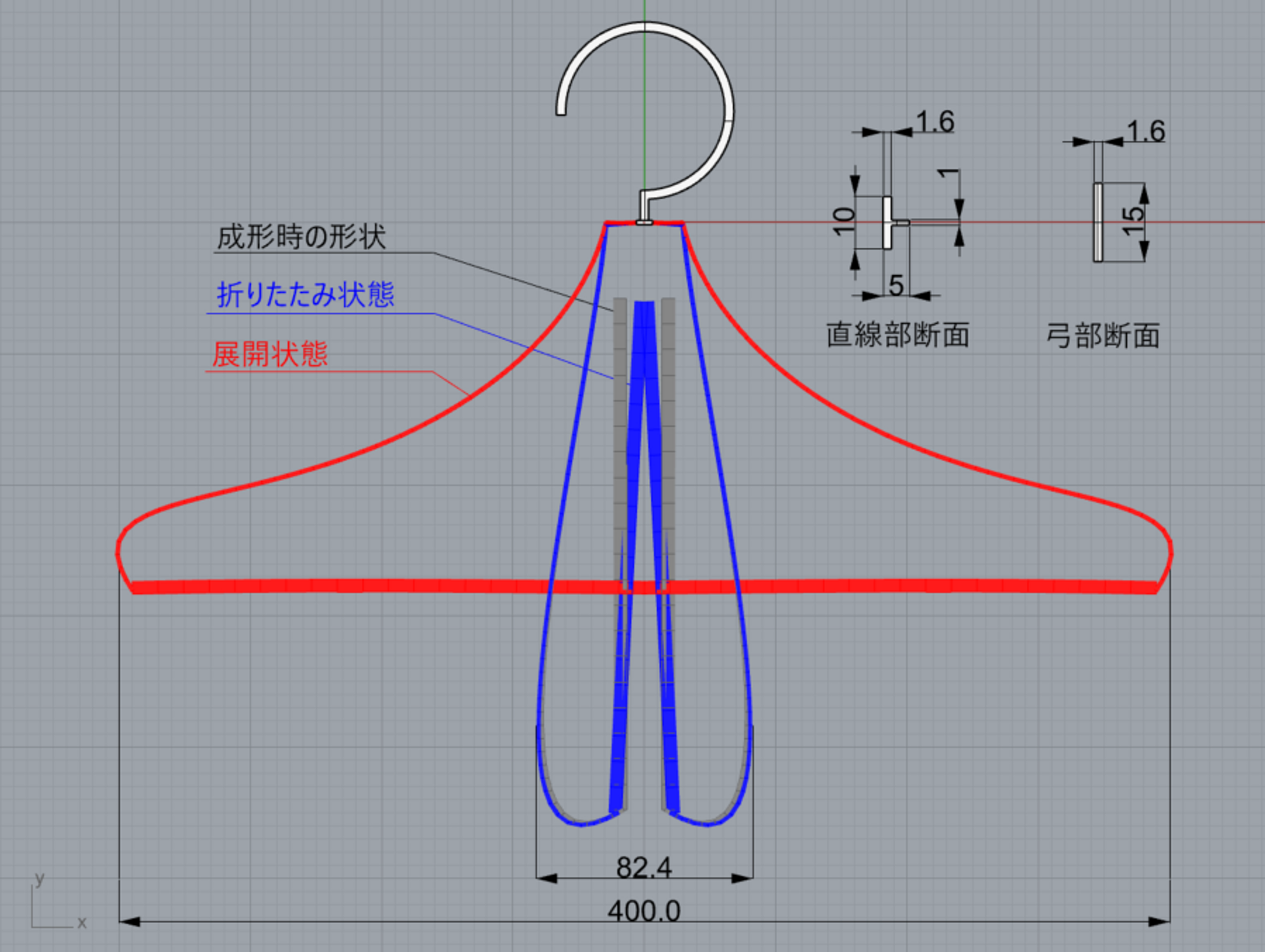
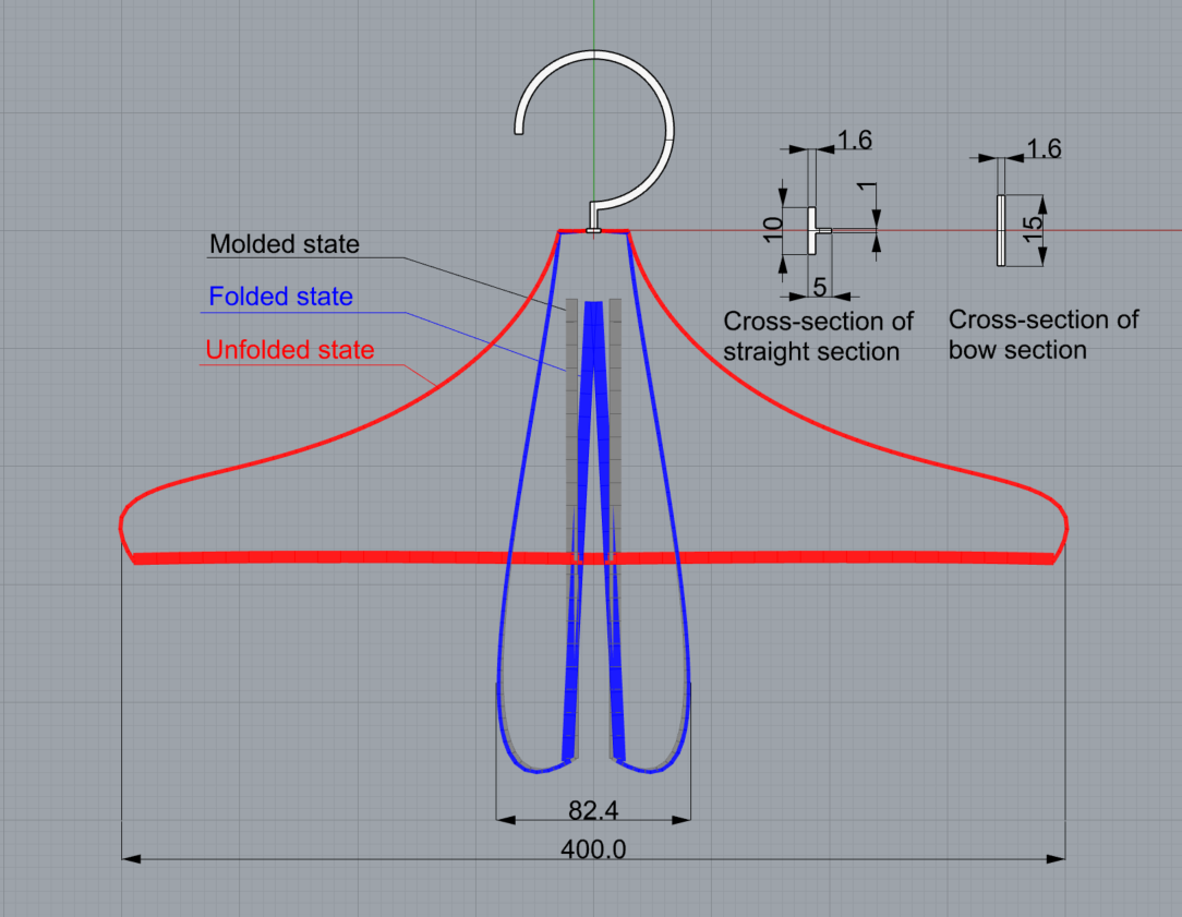
上の3項目確認しながら探索した結果、下の図の形状で要件を満たすことが確認できました。展開状態の形状はハンガーらしい形状で良好です。
弓部の断面形状は、曲げ方向に薄い長方形として曲げたい方向の剛性を下げ、同時に展開操作の操作力と最大応力が狙いの値となるよう寸法を調整しています。直線部は高めの剛性が必要なため、初期的には比較的厚い3.5mm×10mmの長方形としましたが、第2部で述べる成形性の検討から最終的には図に示すT字形状としました。
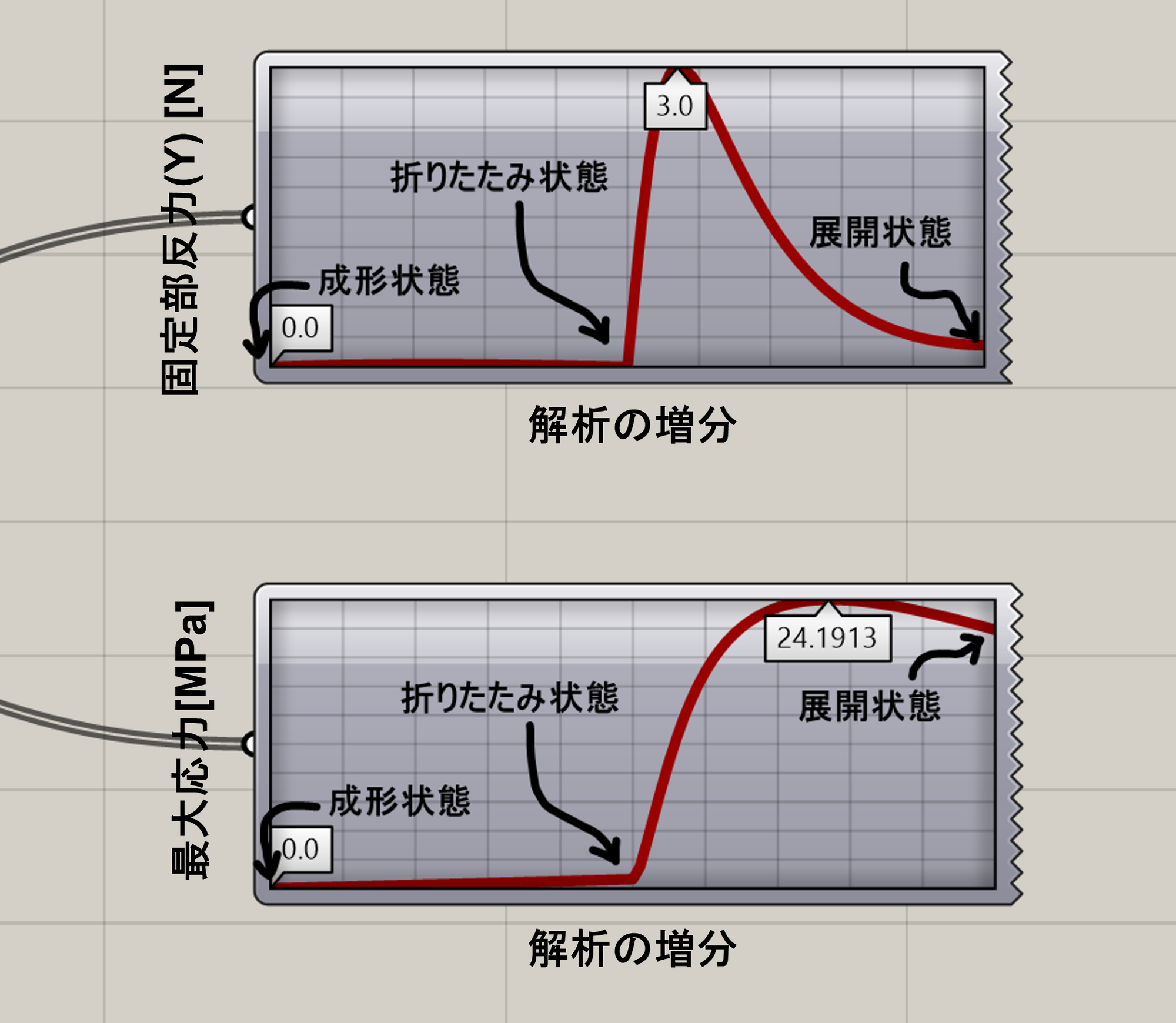
解析における各変形段階の応力と固定部反力(=操作に必要な力)は以下のようになりました。最大値は冒頭で設定した要件(それぞれ3N±10%、31MPa以下)を満たしていることが確認できます。
詳細設計
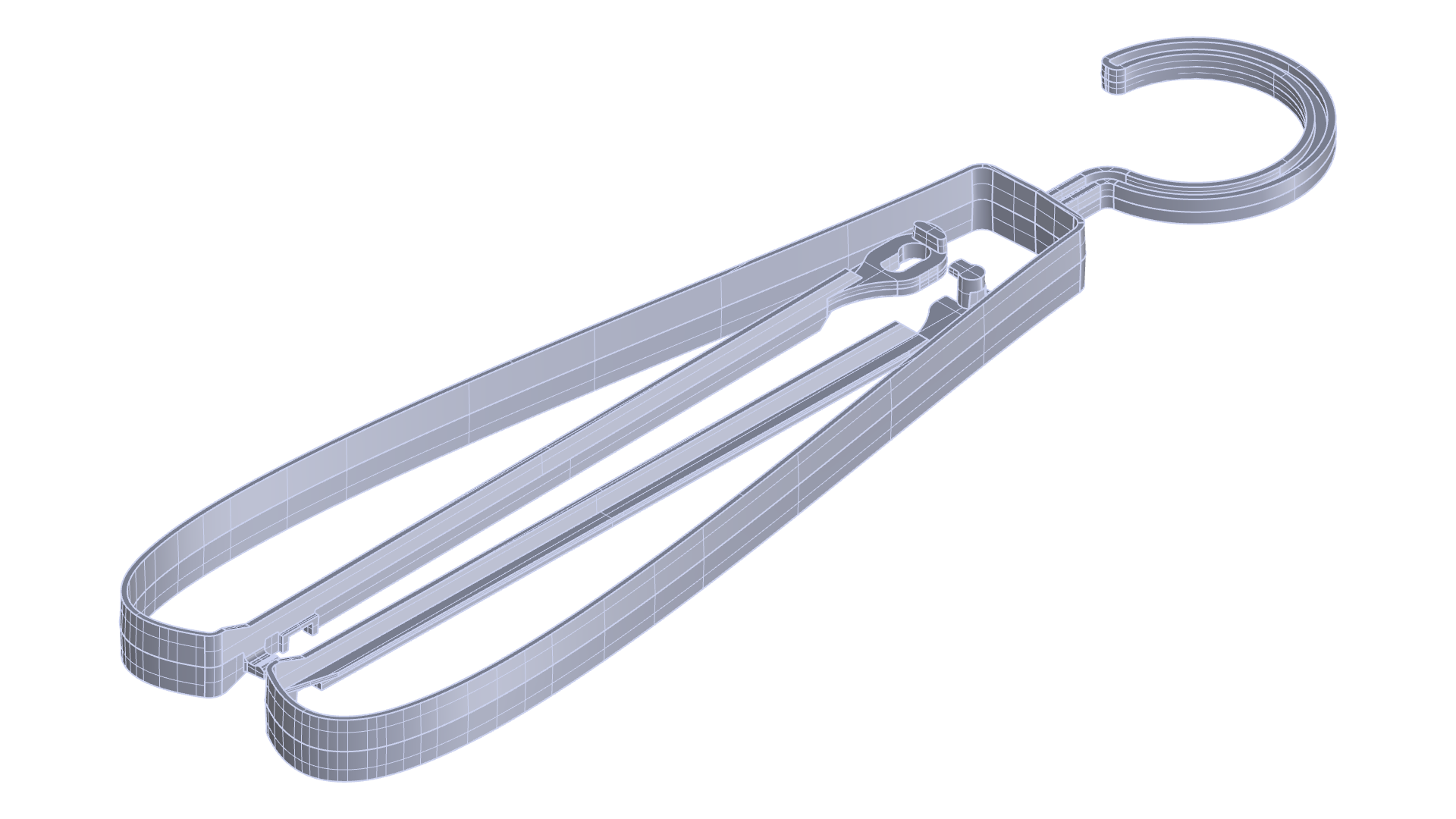
直線部および弓部の形状と断面が決定されたので、詳細設計に進みます。ロック機能のあるヒンジ部、クリープ対策のため閉じた状態で固定できる爪、フック部の肉抜き、抜き勾配などを考慮し、下の形状となりました。成形性を考慮しアンダーカット部が発生しない形状としています。フック部肉抜きについては第2部で詳しく述べます。
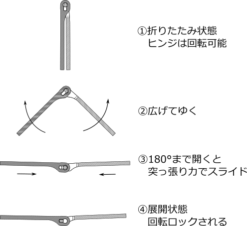
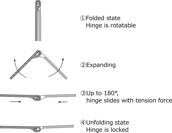
下の断面図に示すように、ヒンジ部は展開すると軸がスライドし、回転がロックされる機構としました。
詳細解析による性能確認
次に詳細設計の3Dデータをもとに、一般的なCAEソフトウェアでソリッド要素での構造解析を行い、応力および反力の確認を行います。境界条件として、フック部付け根を固定し、ヒンジ部の軸および穴部に変位を与えることで、成形時の形状 ⇨ 折りたたみ状態 ⇨ 展開状態 の動きを再現します。
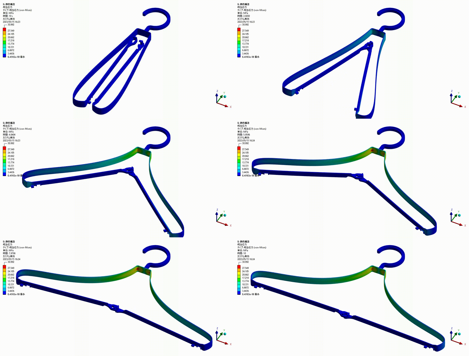
解析の結果、Grasshopper上でのシミュレーションどおり、展開時にハンガー形状となること、反力が3N程度となることが確認できました。最大応力についてはgrasshopper上でのシミュレーションでは24.2MPaでしたが、ソリッド要素での解析では材料線形で32.5MPa(グラフの赤実線)となり、差が出ました。前者は梁要素における最大応力であったため、抜き勾配やRが小さい箇所の応力集中が反映されておらずこのような差が生じていると考えられます。
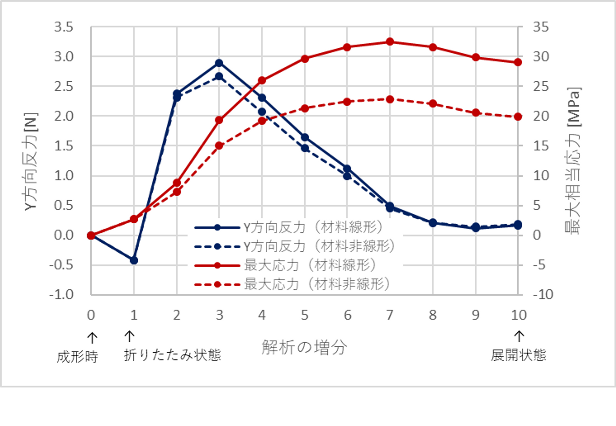
上記の通り、材料線形の計算結果では最大応力が当初想定した許容応力31MPaを超えてしまっていますが、この応力水準では材料の非線形性の影響が小さくありません。材料非線形で解析した結果、最大応力は22.8MPa(グラフの赤破線)となり許容応力以下であるため問題ないと判断しました。
簡易モデルで設計検討を行う際は、解析モデルの忠実度に応じて目標値のマージンを確保しておくことが重要です。今回の事例では、形状を忠実にしたことによる応力の上昇と、材料を忠実にしたことによる応力低下が打ち消し合う結果となりました。
試作
最後に3Dプリンタを使用して試作し、想定通り機能することを確認しました。冒頭の動画をご覧ください。
なお材質をPOMではなくPLAでプリントしたため、状態が遷移する際の反力は設計値よりも低くなっています。
さいごに
本記事では、コンプライアントメカニズムを活用した複数部品の一体化の事例として、折りたたみハンガーの設計について紹介しました。設計の考え方やコンプライアントメカニズムの可能性について感じていただけていれば嬉しいです。
次回は成形性についてより詳しく解説した記事を公開予定です。
Introduction
A mechanism that transmits forces and movements using elastic deformation is referred to as a Compliant Mechanism. Examples of this include springs and snap-fit features in plastic products.
At Nature Architects, we enhance functionality and reduce manufacturing costs by integrating products composed of multiple components using compliant mechanisms.
In this article, we will focus on the design of a "folding hanger" as a case study for utilizing compliant mechanisms. We will present the design approach and discuss specific design flow, including internal tools.
Design Challenge
To enhance portability and storage, many clothes hangers that can be folded are commercially available. Upon examining 10 products listed on an online shopping site, it was found that they generally require assembly of 3 to 10 components based on their images.
In this article, we will design a folding hanger using compliant mechanisms to meet the following objectives:
Design Concepts
- Create a monolithic folding hanger.
- Achieve compactness during molding (efficient use of mold surface area).
The design requirements for the folding hanger are as follows, based on average dimensions of commercially available products:
Design Requirements
- Shape suitable for hanging clothes when unfolded.
- Unfolded width: 400mm.
- Folded width: Below 100mm.
- Thickness (depth in the illustration): Below 15mm.
- Transition load from folding to unfolding state: 3N±10%.
-e1690768967149.png)
Additionally, we consider the following manufacturing constraints:
Manufacturing Constraints
- Shape: Suitable for injection molding without undercuts.
- Material: POM M90-44 (Young's modulus 2500MPa, Poisson's ratio 0.35).
- Allowable stress: 31MPa (to achieve a creep life of 10 years).
Mechanism Selection
Commercially available folding hangers have various deformation mechanisms. Typically, they consist of rigid parts that do not deform and hinge parts that provide rotational freedom. To achieve integration, we need to replace the hinges with compliant mechanisms.
There are various types of hinge shapes used in compliant mechanisms, and the selection depends on the required degrees of freedom, reaction forces, and manufacturing constraints. Sometimes a combination of multiple mechanisms is used.
Created by modifying "Pin Flexure", "Blade Flexure", and "Notch Flexure" © 2017 OptoMechEngineer (Licensed under CC BY-SA 4.0)
In this case, due to the need for planar deformation and significant deformation, we select the Blade Flexure mechanism. While Notch Flexure, which provides only one rotational degree of freedom, would be more precise if purely replacing the hinge function, we prioritize large deformation within the allowable stress range. Hence, Blade Flexure is chosen.
Blade Flexure is often molded as a thin living hinge with a thickness of about 0.2mm to 0.4mm. However, for this folding hanger design, we require a force of approximately 3N to transition from the folded state to the unfolded state. To achieve this, we opt for a thicker and longer dimension to create a bow-like structure for practical use.
Overall Design
Below is an illustration of the hanger's structure, assembly, and opening/closing operation.
-e1690769554582.png)
After molding the left side of the figure, assembling the "Hinge" creates the "Folded State." Subsequently, by manually manipulating the hinge or the straight section, the hanger can be folded and unfolded.
The "Hinge" functions as a hinge when assembled after demolding. While it could be designed as an integrated living hinge, we opted for an assembly-type hinge due to the difficulty of molding in the front-to-back direction and concerns about durability.
The "Bow Section" can be seen as a combination of multiple Blade Flexures. As a standalone mechanism, it has weakened constraints on the degrees of freedom due to its curved connections and significant deformation. In this design, we prioritize the deformation amount, reaction force, and the shape of the hanger when expanded.
The "Straight Section" plays a role in maintaining a constant distance between the hinge and the bottom end of the bow section. To function as a nearly rigid part, it requires sufficient bending rigidity.
Custom Design Environment
How can we design a curved beam that takes on the shape of a hanger after deformation? It is relatively straightforward when the movement is simple or when we can assume small deformations. However, in this case, the beam undergoes significant deformation over a broad range, requiring numerous iterations of shape modifications and analysis result verifications. It becomes challenging to achieve this using the conventional CAD + CAE environment.
At our company, we have independently developed various design environments that operate on the 3D CAD software Rhinoceros through a plug-in called Grasshopper. We can flexibly switch between these environments based on the design problem. (More about Grasshopper can be found in a previous article.)
For this project, we will use an environment where we can model the beam with 2D beam elements and observe deformations in real-time. By utilizing this environment, we can efficiently explore numerous shapes and discover mechanisms that achieve the desired deformations.
Shape Considerations
Using the aforementioned tool, we will proceed to realize the shapes of the bow section and straight section.
After configuring the analysis settings and modeling the shapes during molding, we can immediately run the analysis. This allows us to confirm:
- Shapes in the folded and unfolded states.
- Forces required for deformation.
- Maximum stresses during intermediate stages.
The boundary conditions are set such that the root of the hook section is fixed, the hinge is initially displaced in the X-direction to create the assembly state, and then displaced in the Y-direction to reach the unfolded state.
As a result of exploring while confirming the above three items, we have identified the shape shown in the figure below that meets the requirements. The shape in the unfolded state is well-suited for a hanger.
The cross-sectional shape of the bow section is adjusted to be a thin rectangle in the bending direction to enhance the bending rigidity. For the final design (to be described in Part 2), we opted for the T-shape shown in the figure below.
The stresses and fixed part reaction forces during each deformation stage in the analysis are as follows (the values satisfy the initial requirements of 3N±10% and 31MPa or lower, respectively):
Detailed Design
With the shapes and cross-sections of the straight section and the bow section have been determined, we proceed to the detailed design. Considering the lock function for the hinge, the claw for creep prevention, cutouts in the hook section, and draft angles, we have finalized the shape as shown below. The shape is designed without undercuts for ease of manufacturing. Detailed information regarding the cutout in the hook section will be provided in Part 2.
As shown in the cross-sectional diagram below, the hinge section features a mechanism where the axis slides during unfolding and the rotation is locked.
Performance Confirmation through Detailed Analysis
Next, based on the 3D data from the detailed design, we perform structural analysis using general-purpose CAE software with solid elements to confirm the stress and reaction forces. The boundary conditions are set such that the root of the hook section is fixed, and the axis and hole of the hinge are displaced to replicate the deformation process: molding state ⇨ folding state ⇨ unfolding state.
The analysis results match the simulation in Grasshopper, confirming that the hanger takes on its shape when unfolded, and the reaction force is approximately 3N. The maximum stress from the solid element analysis is 32.5MPa (red solid line in the graph), which differs from the 24.2MPa stress obtained in the Grasshopper simulation. This discrepancy is likely due to the fact that the former represents the maximum stress in the beam elements and does not reflect stress concentrations in regions with small radii and draft angles.
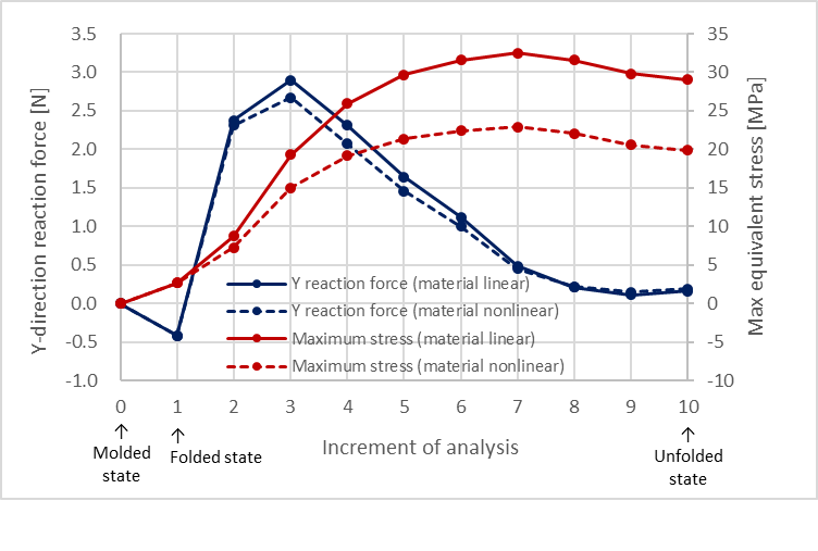
As mentioned above, stress analysis in the linear material model exceeds the initial allowable stress of 31MPa. However, at this stress level, the effects of material nonlinearity are not negligible. The results of the nonlinear analysis indicate that the maximum stress is 22.8MPa (red dashed line in the graph), which is within the allowable stress range, making it acceptable.
When conducting design assessments using simplified models, it is crucial to secure a margin for the target value depending on the fidelity of the analysis model. In this case, the increase in stress due to accurate shape representation and the decrease in stress due to accurate material modeling counterbalance each other, resulting in the observed difference.
Prototype
Finally, we prototyped using a 3D printer to confirm that the mechanism functions as intended. Please refer to the video at the beginning.
Please note that we printed in PLA instead of POM, so the counterforce when transitioning states is lower than the design value.
Conclusion
In this article, we introduced the design of a folding hanger using compliant mechanisms as a case study of integrating multiple components. We hope this article has provided insights into the design approach and the possibilities of compliant mechanisms.
In the next part, we will provide a more detailed explanation of manufacturability.
