
木造住宅大国日本
皆さんはどんなお家に住んでいますか?
戸建て・マンション・アパート,賃貸・持ち家に関わらず日本に居住している方はどこかに住民登録している方がほとんどかと思います。
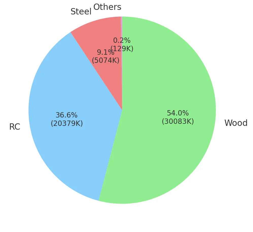
そんな住宅ですが,令和6年:2024年には約79万戸の住宅が建設されそのうち57.1%が木造住宅です。[1]また令和5年:2023年時点で,日本には約5500万戸の住宅が存在しますがその54%は木造という状況です。[2]
そんな皆さんの身近にある木造住宅ですが,みなさんは地震や台風などの外力に対してどの用に設計されているかご存知ですか?
弊社のメンバーは幅広いバックグラウンドを持っており,筆者は建築の構造設計を経験した後にNature architectsに参画しております。構造設計事務所在職時は木造建築を中心に様々な建築物の構造設計を行っておりました。
今回のTechBlogではそんな木造住宅の構造設計に焦点を当て,設計方法の概説やお手軽設計ツールの開発,前述したツールを使用した最適設計を行ってみました。
低層木造住宅における構造設計の概要
建築物を建設する際には,建築基準法(以下「法」)および建築基準法施行令(以下「令」)に基づき,各種設計図書や構造計算書を作成する必要があります。[3]
その中でも,低層木造住宅の構造設計において特に重要となるのは,以下の2つの規定です。
- 法第20条
- 令第40条~第49条
簡単に説明すると,法第20条は建築物の規模や仕様に応じた構造設計の方法(設計ルート)を規定しています。規模が大きい建築物や,特定の仕様を満たさない建築物には,より精緻な解析方法が法的に求められます。一方で今回主題とする木造建築物においては,延床面積・階数・高さ・耐力壁(量および偏心状況)などの規定を遵守することで,手計算でも算出可能な簡易的な検討により設計を行うことができます。
令第40条~第49条は,木造建築物の仕様規定を定めたものです。仕様規定とは,建築物の材料・寸法・構法について具体的に定め,それに従うことを求める規定です。各仕様の詳細な解説は他の文献に譲りますが,ここでは地震や台風などの外力に対する安全性を確保するうえで重要な 「令第46条」 について説明します。
令第46条と耐力壁の設計
令第46条 は「構造耐力上必要な軸組等」に関する規定です。この条文では,地震や強風(台風)による外力に対して,必要な耐力壁の量を確保するとともに,それを釣り合いよく配置することを求めています。
ここで 「壁倍率」 と 「壁量」 という重要な概念が登場します。
壁倍率とは
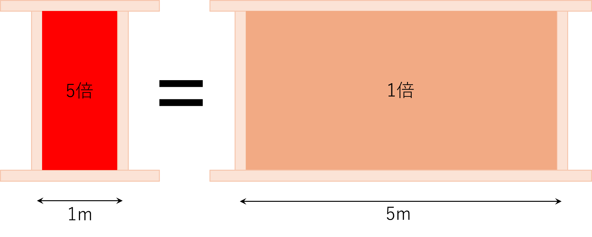
壁倍率とは,壁材料や接合具などの仕様に与えられる耐力壁強度の数値です。基準となる 壁倍率1.0倍 は,単位長さ1mの耐力壁が1.96kN(200kgf)のせん断力まで許容できることを意味します。この壁倍率に応じて,各耐力壁の許容せん断耐力が変化します。例をあげると以下のような1mの5倍壁と5mの1倍壁は同じ許容せん断耐力を持っています。ただし高倍率壁の性能を発揮させるためには浮き上がり防止の適切な仕様の金物が必要になってくるため,コストが嵩んだり周辺架構への影響も大きくなるためなるべく小さい倍率の壁を使用するのが得策ではあります。
壁量とは
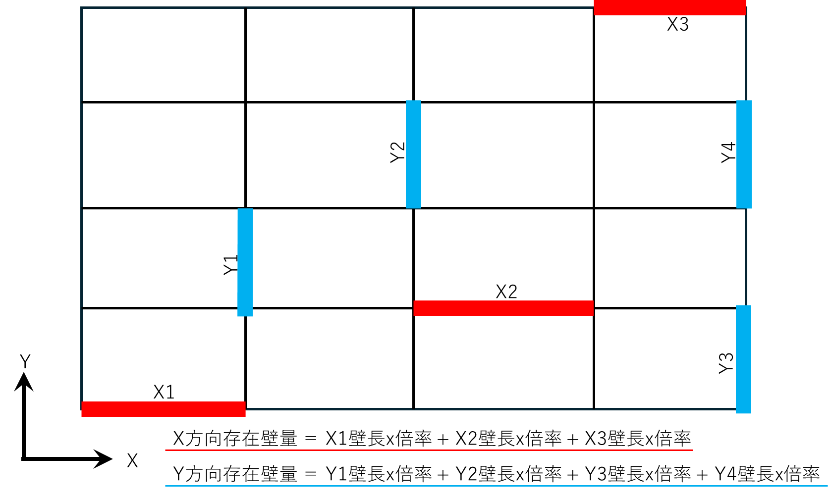
壁量は建築物の水平方向耐力の指標であり,設置された各耐力壁の「壁倍率 × 壁長さ」の合計値として求められます。耐力壁は主として面内方向にしか効かないため,壁量は方向別に算出されます。一般的な矩形平面の建築物では,建物の0°方向と90°方向の2方向に分けて算出されます。ここでは後述する基準壁量nLwと表記を分けるため存在壁量Lwと呼びます。
安全性の確認
上記の存在壁量に対して,地震や台風などの外力に基づいて算出される 「基準壁量nLw」 が存在します。この基準壁量nLwと存在壁量Lwを比較し,建物の存在壁量Lwが基準壁量nLwを上回っていることを確認することで建築物の安全性を確保します。
\(\text{壁量検定比} = \frac{L_w}{n L_w} > 1.0 \tag{1}\)
なお2025年4月に基準壁量の算出基準が変更 されるため細かな算定方法の詳細は他の文献に譲りますが,基本的には 単位面積あたりの必要壁量(cm/㎡)に各階の床面積A(㎡)を乗じることで算出 されます。
\(\text{基準壁量} \ nL_w \ (\text{cm}) = \text{単位あたり必要壁量} \ unL_w \ (\text{cm/㎡}) \times \text{床面積} \ A_f \ (\text{㎡}) \tag{2}\)
また強震時に建物がねじれて挙動し無いように,建物重心位置と耐力壁剛性中心位置の関係からなる偏心率が基準値以下であることを確認します。または簡易的な4分割法という算定手法がありますが,文が長くなるためここでは割愛します。
以上を確認することで低層木造住宅構造設計の3割くらいを実施することが出来ます。
木造壁量計算関係計算コンポーネント作成
前述した各検討をお手軽に行えると皆さん幸せになると思います。
そこで弊社で頻繁に使用している「Rhinoceros+Grasshopper」の環境を使用します。この環境で各検討を実行できる木造建築物設計コンポーネント群を作成しました。以下よりDL可能です。まだ評価がないので誰か五つ星評価をしておいてください!
https://www.food4rhino.com/en/app/otter

機能としては前述した各検定を一通り網羅したものになっており,①風荷重受圧面積の算定,②基準壁量の算定,③各平面の重心算定及び四分割法参入位置の図化,④各耐力壁の角度補正及び存在壁量の算出,⑤各壁量検定,⑥偏心検定,⑦耐力壁端部引張力の算定が可能となっています。
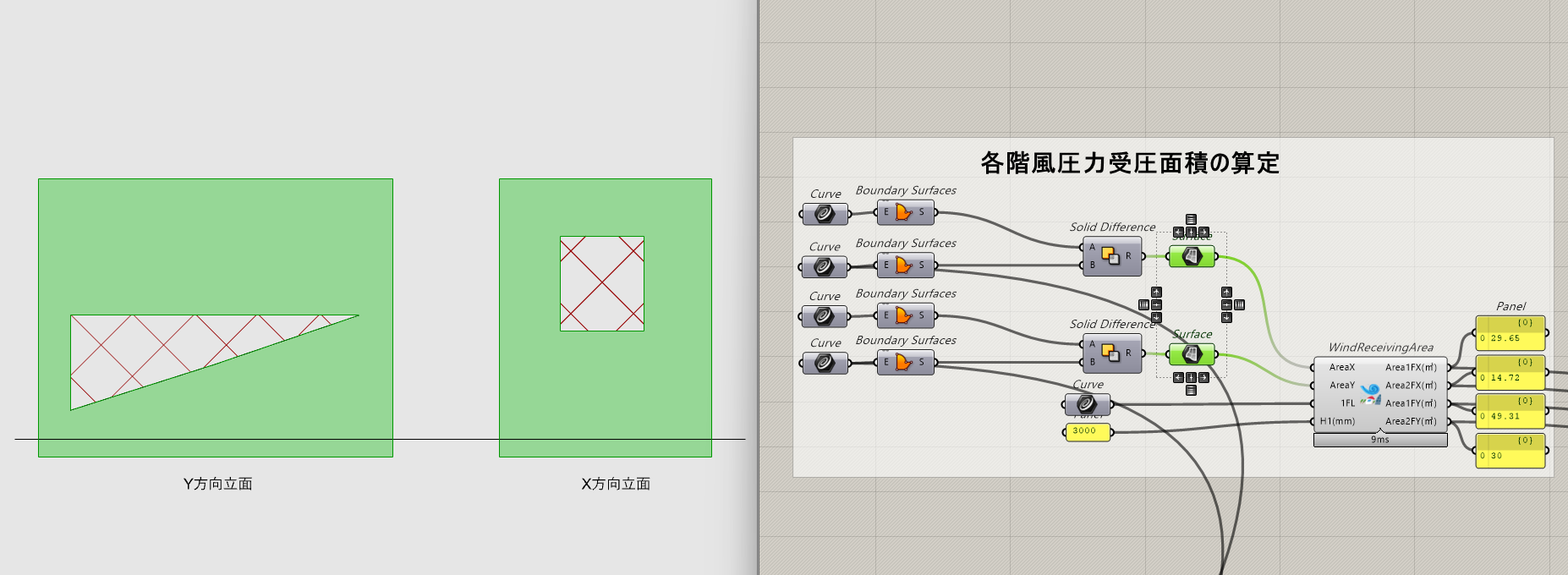
立面のサーフェスと1FLのCurveを入力することで各方向,各階で使用する風荷重受圧面積の算定が可能です。
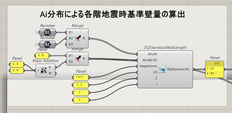
各階の面積(㎡)及び単位床荷重(kN/㎡),数値として最高高さ(m)と総せん断力係数C0,地域係数Z,重要度係数Iを入力することで基準壁量が算出出来ます。
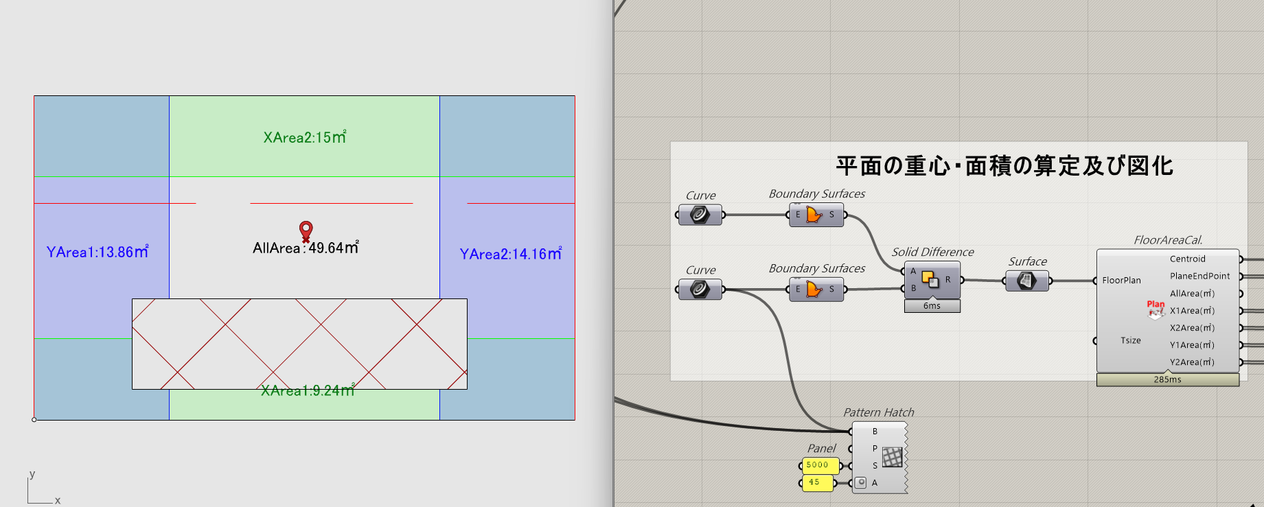
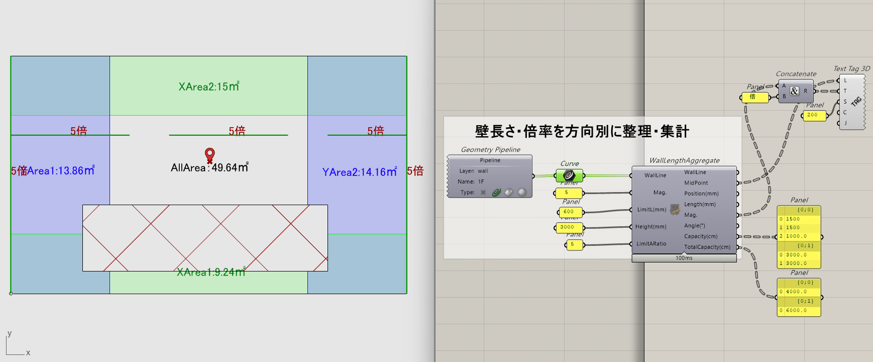
耐力壁位置と壁倍率をTree形式で入力すると,異なる倍率の壁もいっぺんに考慮可能なので便利です。
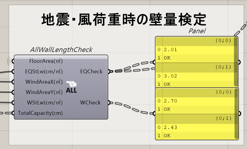

偏心率の検定においては令46条2項ルートで規定されている0.3を基準として検定を行っています。
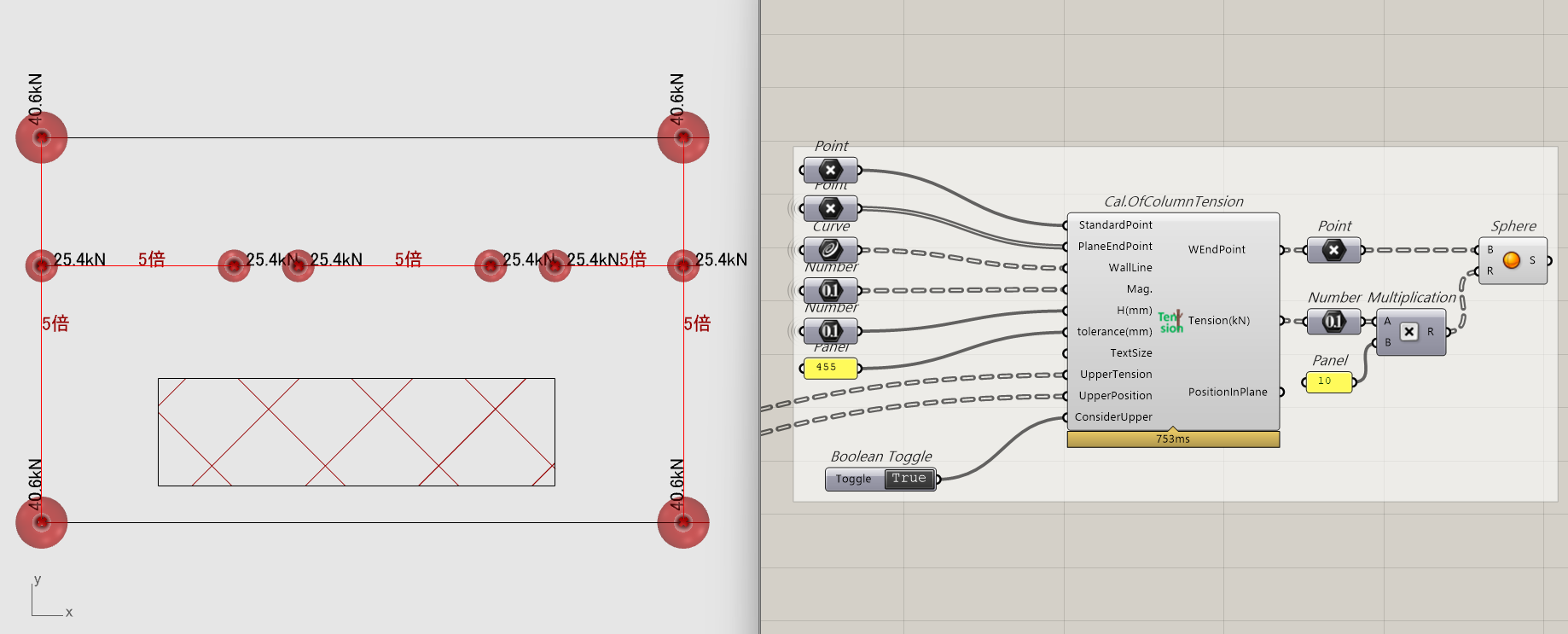
上階の引張力及び位置を自動で判定して下階の引張力に足し合わせることも可能です。
その他耐力壁シアキー用のアンカーボルト数の自動計算や,25年4月の法改正で追加される「座屈を加味した最小柱サイズの算定・検定」,「鉛直方向壁量充足率の検定」も可能となっています。
現在も開発作業は続いており,詳細計算法による耐力壁倍率の算定や耐力壁ブレース置換断面算定,引きボルトによる木造ラーメン接合部剛性及び耐力算定コンポーネントの追加を画策しています。
壁量計算・偏心率最適化
せっかくコンポーネントを作成したので何か住宅の設計してみたいものです。
ちょうどO阪に木造戸建て住宅を購入していたエンジニアのO氏に協力を打診し,住宅の平面を提供いただきました。素敵な住宅です。
敷地周辺環境と住居環境を分析すると以下のようなことが分かります。
敷地の南側は庭があり東側には公園が存在するため,開口部が多くなり必然的に耐力壁が減少します。反対に西側・北側には隣家が存在するため開口部は少なく,耐力壁は比較的潤沢に設置出来ます。更に1階の北側には水回りの小空間が存在するため,部屋境に耐力壁を設置することが可能です。また1階部分を家族共用の大きな空間とし2階を個々人の個室空間としているため,相対的に1階部分の壁が少なくなります。
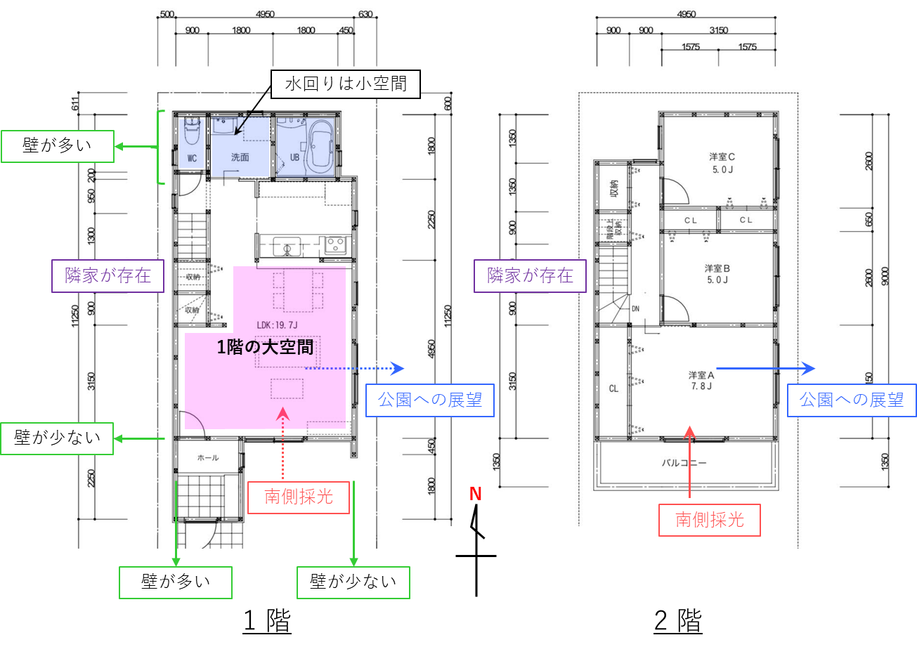
平面的にシンプルで耐力壁箇所もそこまで多くないため,上述したコンポーネントを使用して手作業で各検定を満たす倍率・耐力壁位置を探索することも可能です。ただ折角なので弊社エンジニアが制作した最適化コンポーネント”Tunny”[4]を使用して耐力壁倍率の最適化を行います。
以下のセットアップを使用して最適化を行っていきます。
- 対象平面:1階
- 最適化手法:NSGAⅡ
- 目的関数:偏心率最小化,各壁倍率の総和最小化(2目的)
- 変数:各壁倍率(18変数)
- 制約条件:壁量検定比1.0以上,偏心率0.3以下
偏心率は建物の耐力要素の平面的な偏り具合を表し,強震時の倒壊率と相関するため目的関数に設定しています。
各壁倍率の総和を目的関数に設定しているのは,壁倍率が大きな耐力壁になると壁端部柱に取り付ける金物のコストが増加するためです。壁倍率が大きくなるほど,耐力壁端部柱に作用する引張力も増加し,それに対応する高い引張耐力を持つ金物が必要となります。さらに,建物下の基礎や地盤への影響も大きくなることからこのように設定しています。
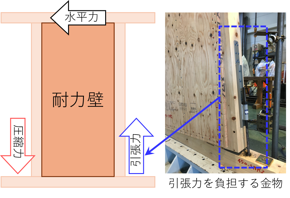
変数は各壁(18箇所)の壁倍率を設定しています。変数が3^18と多いですが,取り得る倍率は各壁仕様を考慮し3つ(2.5倍・5.0倍・7.0倍)に限定し取りうる組み合わせを減らしつつ最適化により効率的に解を探索しています。
制約条件は壁量検定比と偏心率検定として,各検定がNGとなる個体は最適化から弾くよう設定しています。
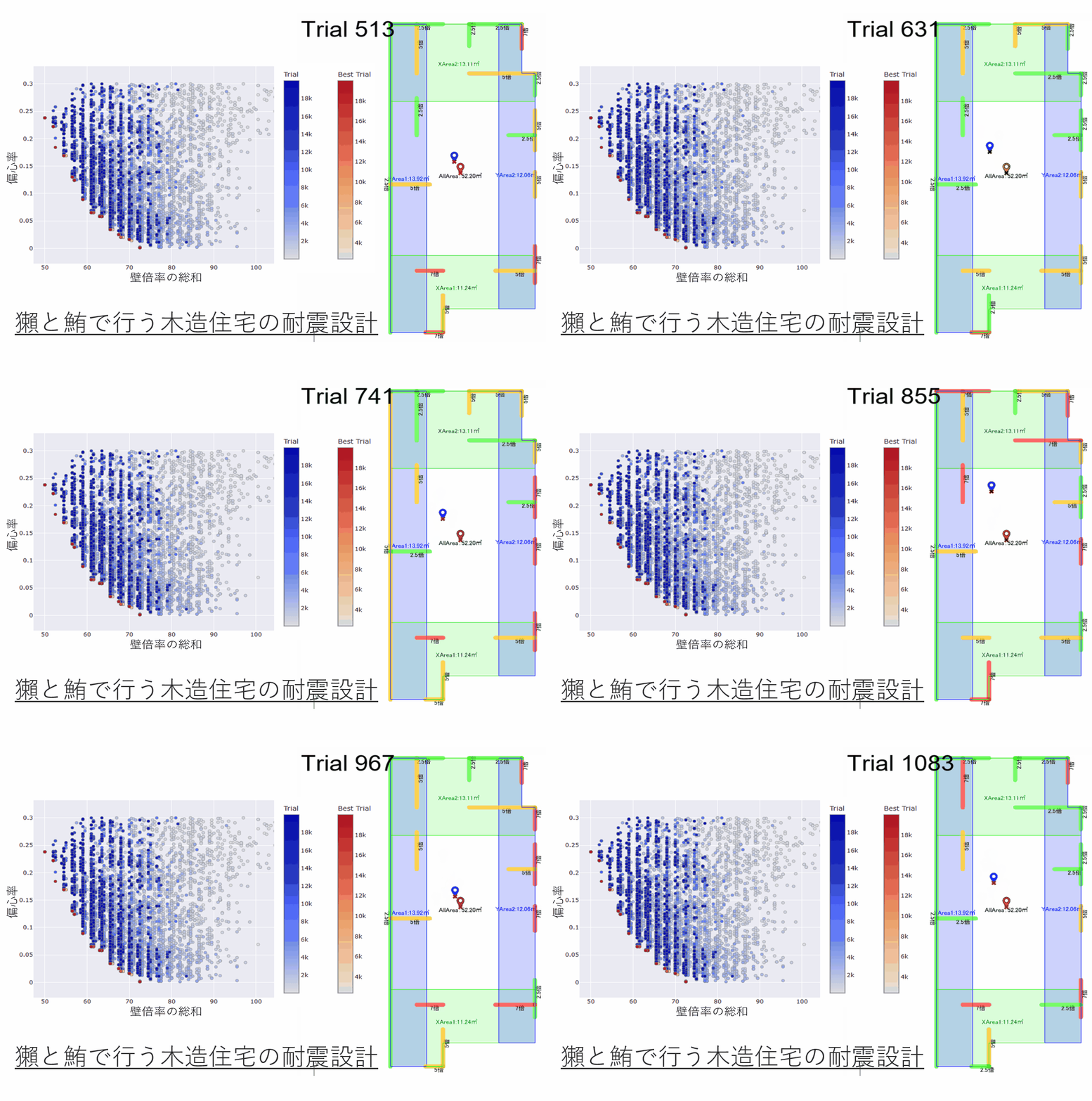
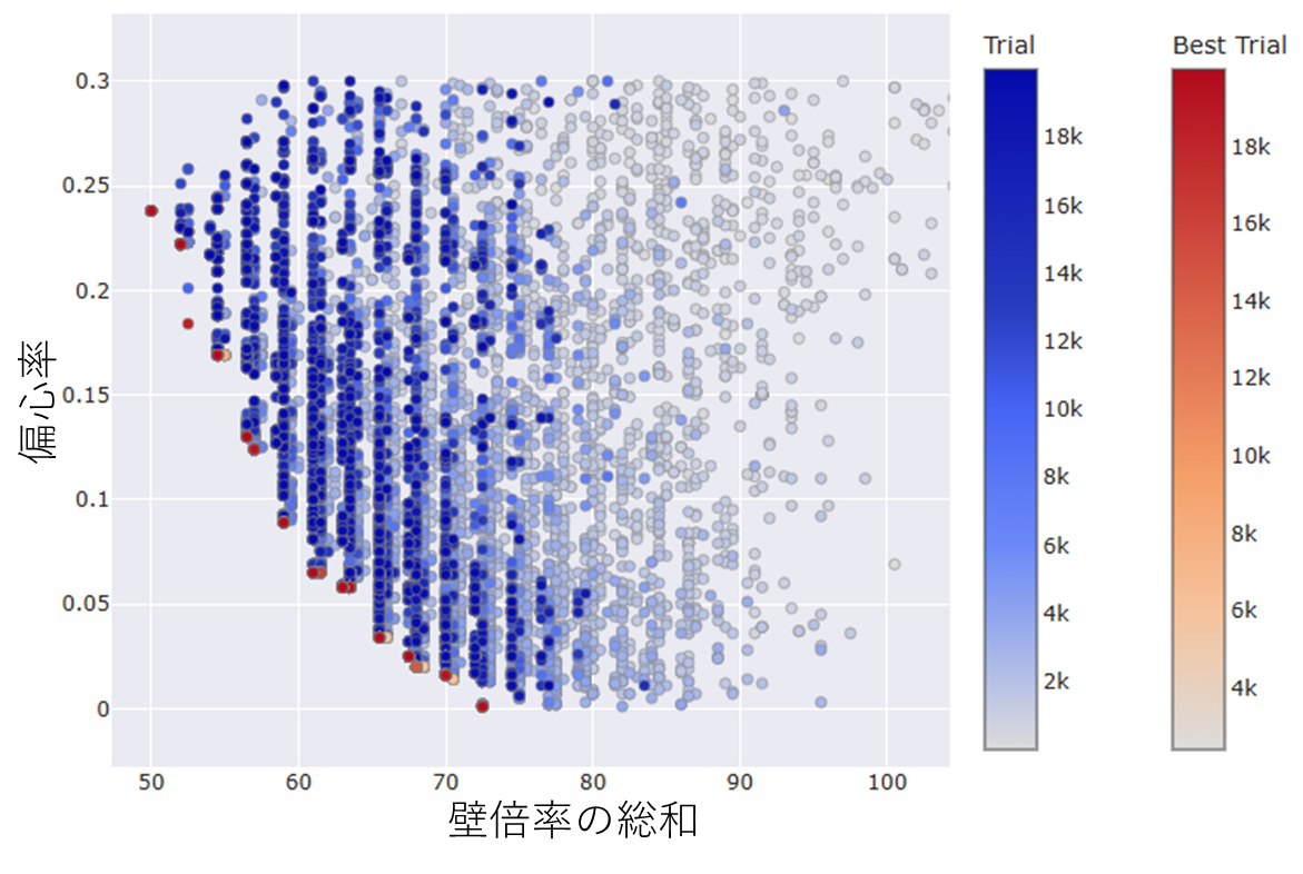
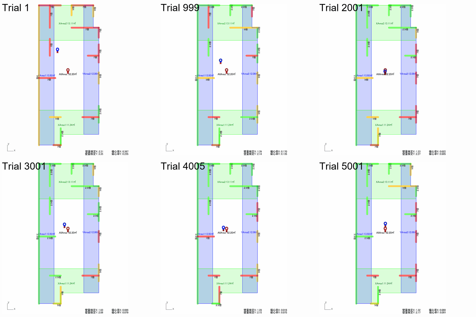
以下が最適化結果及び最適化経過となります。
きれいにパレートフロントが出来ているため,上記した条件では壁倍率の総和と偏心率はトレードオフの関係があるようです。
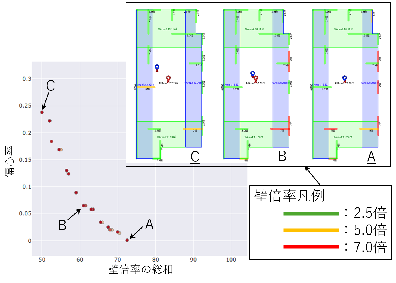
パレートフロントの一部個体を確認して,各壁倍率状況を見てみましょう。
最も偏心率が小さいAの個体においては開口部が多い南側・東側の高倍率の7倍の壁を用いて偏心率をほぼ0におさめています。しかしながらY方向の壁量検定比は2.17となっており壁量検定に大きな余裕がある状況です。
一方,Cの個体は全体的に最低倍率の2.5倍壁で抑えつつも,南側の壁を部分的に高倍率のものに変更しています。こちらは壁量検定比がY方向1.62と余裕が小さくなったものの偏心率は0.24と比較的大きいものです。
中間のB案に関してはA・Cパターンの間のような倍率分布となっています。
Tunnyを使用した最適化により各値の分布状況・検定余裕度を俯瞰して確認できるようになり,その中から設計者が状況に応じて最良解を選択することが可能になります。
まとめ
いかがだったでしょうか?
低層木造住宅設計の重要な概念を理解した上で,コンポーネントを使用すれば誰でも耐震設計が可能になりました!実際には地盤の状況,梁などの横架材設計等があるため一筋縄では行きませんが。
また今回のブログでは提案しきれませんでしたが,平面上での最適な耐力壁位置の最適化も可能と思います。
人生100年の時代,35年ローンの信用情報に問題無い方はぜひお気軽に自宅の耐震設計にトライしてみてください!
参考文献
[1]国土交通省. "報道発表資料: 建築着工統計調査報告(令和6年計分)". URL(2025/02/26閲覧)
[2]総務省統計局. "2023年住宅・土地統計調査 調査計画". URL(2025/02/26閲覧)
[3]稲山 正弘. ”中大規模木造建築物の構造設計の手引き 改訂版”. 2023. 彰国社.
[4]Food4Rhino. "Tunny – Optimization Plugin for Rhino/Grasshopper". URL(2025/02/26閲覧)
Japan, a country of wooden houses
What kind of house do you live in?
Regardless of whether you live in a house, condominium, or apartment, or whether you rent or own your house, most of you are registered as a resident somewhere in Japan.
In 2024, approximately 790,000 housing units will have been constructed, of which 57.1% are wooden houses. [In 2023, there will be approximately 55 million housing units in Japan, 54% of which will be made of wood. [2] In 2023, 54% of these houses will be made of wood.
Wooden houses are all around us, but do you know how they are designed to resist external forces such as earthquakes and typhoons?
The members of our firm come from a wide range of backgrounds, and the author joined Nature architects after working in the field of structural design for architecture. While working for a structural design firm, I was involved in the structural design of a variety of buildings, with a focus on wooden structures.
In this TechBlog, we focus on the structural design of wood-frame houses, and we have outlined the design method, developed an easy-to-use design tool, and performed an optimal design using the aforementioned tool.
Overview of Structural Design in Low-rise Wooden Houses
When constructing a building, various design documents and structural calculations must be prepared in accordance with the Building Standards Law (hereinafter referred to as “the Law”) and the Building Standards Law Enforcement Order (hereinafter referred to as “the Order”). [3]
Among these, the following two regulations are particularly important for the structural design of low-rise wooden houses.
- Article 20 of the Law
- Article 40-49 of the Order
Briefly, Article 20 of the Law specifies structural design methods (design routes) according to the size and specifications of buildings. For larger buildings or those that do not meet certain specifications, more elaborate analysis methods are legally required. On the other hand, for wooden buildings, which are the subject of this study, design can be performed by a simple study that can be calculated by hand, provided that the total floor area, number of stories, height, bearing walls (quantity and eccentricity), etc., are observed.
Articles 40-49 of the Order set forth the specifications for wooden buildings. Specifications are specific regulations that specify materials, dimensions, and construction methods of buildings and require compliance with these specifications. Detailed explanations of each specification are given in other literature. This section describes Article 46 of the Order, which is important for ensuring safety against external forces such as earthquakes and typhoons.
Article 46 of the Order and Design of Load-bearing Walls
Article 46 of the Order stipulates the “necessary structural framing, etc.”. This article requires that the required amount of bearing walls be secured against external forces caused by earthquakes and strong winds (typhoons), and that they be arranged in good proportion.
This is where the important concepts of “wall ratio” and “wall volume” come into play.
What is wall ratio?
The wall ratio is a numerical value of bearing wall strength given to specifications such as wall materials and joints. The standard wall ratio of 1.0 means that a bearing wall with a unit length of 1 m can withstand shear forces of up to 1.96 kN (200 kgf). The allowable shear capacity of each bearing wall varies according to the wall ratio. For example, a 1m 5x wall and a 5m 1x wall have the same allowable shear capacity. However, in order to achieve the performance of a wall with a high wall modulus, hardware with appropriate specifications to prevent lifting is required, which increases the cost and has a greater impact on the surrounding structure.
What is wall volume?
The wall mass is a measure of the horizontal bearing capacity of a building and is calculated as the sum of “wall ratio x wall length” for each installed bearing wall. Since bearing walls are mainly effective only in the in-plane direction, the wall mass is calculated for each direction. For a typical rectangular building, the wall mass is calculated in two directions, one at 0° and the other at 90°. In this section, we refer to the wall volume Lw as the existing wall volume to distinguish it from the standard wall volume nLw, which is described later.
Confirmation of safety
In addition to the existing wall mass described above, there is a “reference wall mass nLw” that is calculated based on external forces such as earthquakes and typhoons. By comparing the reference wall mass nLw with the existing wall mass Lw and confirming that the existing wall mass Lw of the building exceeds the reference wall mass nLw, the safety of the building is ensured.
\(\text{WALL TEST RATIO} = \frac{L_w}{n L_w} > 1.0 \tag{1}\)
The details of the calculation method will be referred to other literature because the standard for calculating the standard wall mass will be changed in April 2025.
\(\text{Standard wall volume} \ nL_w \ (\text{cm}) = \text{Required wall volume per unit} \ unL_w \ (\text{cm/㎡}) \times \text{FLOOR AREA} \ A_f \ (\text{㎡}) \tag{2}\)
To prevent the building from twisting during a strong earthquake, the eccentricity, which is the relationship between the center of gravity of the building and the center of rigidity of the bearing walls, must be less than the standard value. Alternatively, there is a simplified calculation method called the 4-division method, but it is omitted here because of its lengthy description.
By confirming the above, about 30% of the structural design of a low-rise wooden house can be carried out.
Creation of calculation components related to wooden wall calculation
We believe that everyone will be happy if each of the aforementioned studies can be performed easily.
Therefore, we will use the “Rhinoceros+Grasshopper” environment that we frequently use in our company. We have created a set of wooden building design components that can perform each study in this environment. It can be downloaded from the following link. Please someone give it a five star rating as it has not been rated yet!
https://www.food4rhino.com/en/app/otter
It is capable of (1) calculation of wind load bearing area, (2) calculation of standard wall volume, (3) calculation of the center of gravity of each plane and diagramming of the entry position of the quadrant method, (4) angle correction of each bearing wall and calculation of existing wall volume, (5) each wall volume test, (6) eccentricity test, (7) calculation of bearing wall edge tensile force.
Wind load bearing area can be calculated for each direction and each floor by inputting the elevation surface and 1FL curve.
The standard wall mass can be calculated by entering the area of each floor (m2), the unit floor load (kN/m2), the maximum height (m), the total shear force coefficient C0, the regional coefficient Z, and the importance coefficient I.
It is convenient to input the location of load-bearing walls and wall magnification in a tree format so that walls with different magnifications can be considered at the same time.
The eccentricity is tested based on 0.3, which is specified in Article 46, Paragraph 2, Route of the Order.
The tensile force and position of the upper floor can be automatically determined and added to the tensile force of the lower floor.
In addition, the number of anchor bolts for shear keying of bearing walls is automatically calculated, and “calculation and testing of minimum column size taking buckling into account” and “testing of vertical wall mass sufficiency ratio”, which will be added in the April 2013 revision of the law, are also available.
Development work is still ongoing, and we are planning to add components for calculating load-bearing wall magnification using the detailed calculation method, calculating the cross section of a load-bearing wall brace replacement, and calculating the stiffness and load-bearing capacity of wooden ramen joints using pull-bolts.
Wall volume calculation and eccentricity optimization
Now that we have created the components, we would like to design some housing.
We approached Mr. O, an engineer who had just purchased a wooden detached house in O-han, and asked him for his cooperation, and he provided us with a plan of the house. It is a beautiful house.
An analysis of the site surroundings and the residential environment reveals the following.
On the south side of the site, there is a garden and a park on the east side, which leads to many openings and inevitably reduces the number of load-bearing walls. Conversely, on the west and north sides, there are few openings due to the presence of neighboring houses, and the bearing walls can be installed relatively abundantly. In addition, a small space for water supply is located on the north side of the first floor, which makes it possible to install load-bearing walls at the room borders. In addition, since the first floor is a large space shared by the family and the second floor is a private space for each individual, the walls on the first floor are relatively small.
Since the plan is simple and there are not that many bearing wall locations, it is possible to manually search for the magnification factor and bearing wall locations that satisfy each test using the above-mentioned components. However, since this is a good opportunity, we will use the optimization component “Tunny” [4], which was created by our engineers, to optimize the load-bearing wall magnification.
The following setup will be used for optimization.
- Target plane: 1st floor
- Optimization method: NSGA II
- Objective function: Minimize eccentricity, minimize sum of each wall ratio (2 objectives)
- Variables: Each wall ratio (18 variables)
- Constraints: Wall mass test ratio of 1.0 or more, eccentricity of 0.3 or less
Eccentricity is set as an objective function because it represents the degree of bias in the plane of the building's load-bearing elements and is correlated with the collapse rate during a strong earthquake.
The reason why the sum of each wall ratio is set as the objective function is because the cost of hardware to be attached to the columns at the wall ends increases when the wall ratio is large for bearing walls. As the wall ratio increases, the tensile force acting on the column at the end of the bearing wall also increases, requiring hardware with high tensile strength. In addition, the effect on the foundation and ground beneath the building also increases.
The variable sets the wall ratio for each wall (18 locations). At first glance, this may seem like a lot of variables, but the number of possible combinations is not that large because there are three possible magnification factors (2.5x, 5.0x, and 7.0x) depending on the wall specification.
The constraint conditions are the wall mass test ratio and the eccentricity test, and the individual specimens that fail each test are omitted from the optimization.
The following are the optimization results and the optimization process.
Since the Pareto front is formed nicely, there seems to be a trade-off relationship between the sum of the wall ratio and the eccentricity under the above conditions.
Let's check some of the Pareto Front units to see the status of each wall magnification.
In case A, which has the smallest eccentricity, the eccentricity is kept to almost zero by using high magnification 7x walls on the south and east sides, where there are many openings. However, the wall mass test ratio in the Y direction is 2.17, which means that there is a large margin for wall mass test.
On the other hand, the wall of unit C is generally kept at 2.5 times the minimum wall ratio, but the south wall is partially changed to a wall with a higher ratio. This one has a relatively large eccentricity ratio of 0.24, although the wall mass test ratio is now 1.62 in the Y direction, which is a smaller margin.
The middle plan B has a magnification distribution similar to that between patterns A and C.
Optimization using Tunny enables the designer to check the distribution of each value and the test margin from a bird's-eye view and to select the best solution according to the situation.
summary
How was it?
Now that you understand the important concepts of low-rise wood-frame house design, anyone can use the components to design an earthquake-resistant house! In reality, however, it is not a simple task because of the ground conditions, the design of beams and other horizontal members, and other factors.
In addition, although I could not fully propose it in this blog, I think it is possible to optimize the optimal location of bearing walls on a flat surface.
In this age of 100-year life expectancy, if you have no problem with your credit report for a 35-year loan, please feel free to try earthquake-resistant design for your home!
References
[1]Ministry of Land, Infrastructure, Transport and Tourism. “Press Release: Report on Statistical Survey of Construction Starts (2024).". URL(2025/02/26閲覧)
[2]Statistics Bureau, Ministry of Internal Affairs and Communications. “2023 Housing and Land Survey Survey Plan.”. URL(2025/02/26閲覧)
[3]Inayama, Masahiro. "Guidance for Structural Design of Medium and Large Wooden Buildings, Revised Edition ”*. Shokoku-sha. 2023.
[4]Food4Rhino. "Tunny – Optimization Plugin for Rhino/Grasshopper". URL(2025/02/26閲覧)
