
はじめに
弾性変形を活用するコンプライアントメカニズムやメカニカルメタマテリアルでは,意図しない方向の変形は好ましくない場合があります。そのため,変形が生じてほしくない方向には十分な剛性を有していることが要求されます。このようにコンプライアントメカニズムは剛性異方性が基本となって設計されます。今回は,材料異方性ではなく,マクロな剛性が異方性を有する構造について述べます。
想定の変形挙動となる構造を設計するためには各方向の剛性,すなわち部材の変形と負荷荷重の関係性を把握することが重要となります。この関係性は有限要素法を用いても計算可能ですが,最適化のために多数回の試行を行うにはなるべく簡易的なモデルを用いて計算時間を削減することが重要となります。本記事では,基本的な材料力学や剛体力学を活用した,コンプライアントメカニズム挙動の簡易計算方法について紹介します。
スライダー構造
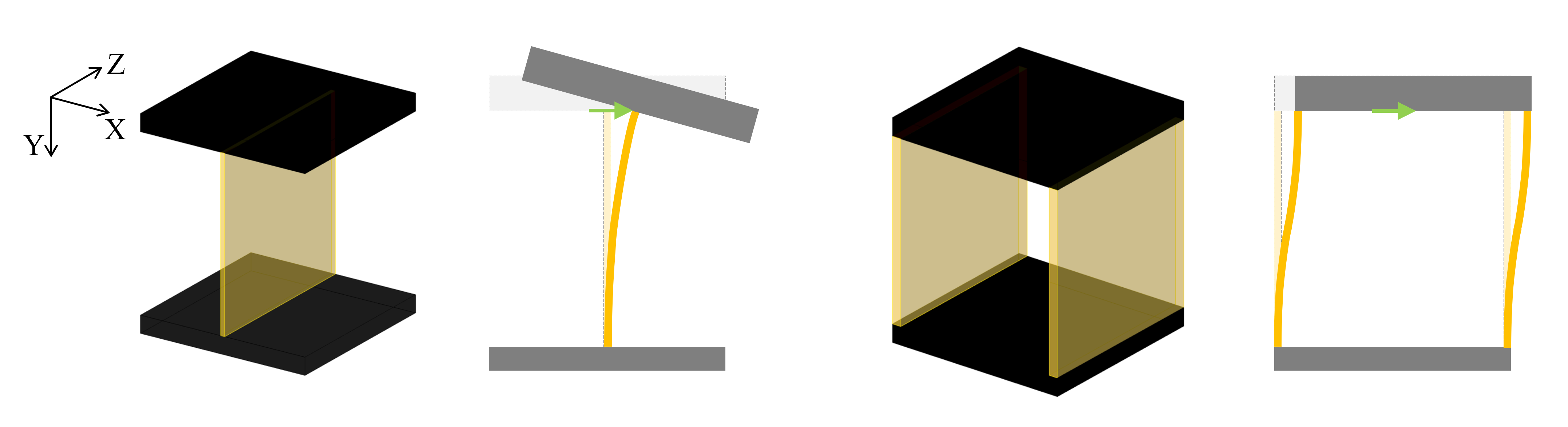
コンプライアントメカニズムを構成する要素として頻繁に用いられる構造にスライダー構造(Parallel-guiding mechanism)と呼ぶ構造があります。以前の記事でも紹介しているように,一方向以外の変形に対しては剛性が高く,並進移動を誘導する構造となっています。変形自由度を拘束する考え方でもこの構造を導くことはできますが,今回は剛性特性について数式を用いて解説したいと思います。
問題設定
構造を考える上での条件を次のように設定します。今回は,20mm立方の設計空間において上下の剛体部品を接続する構造を考えます。
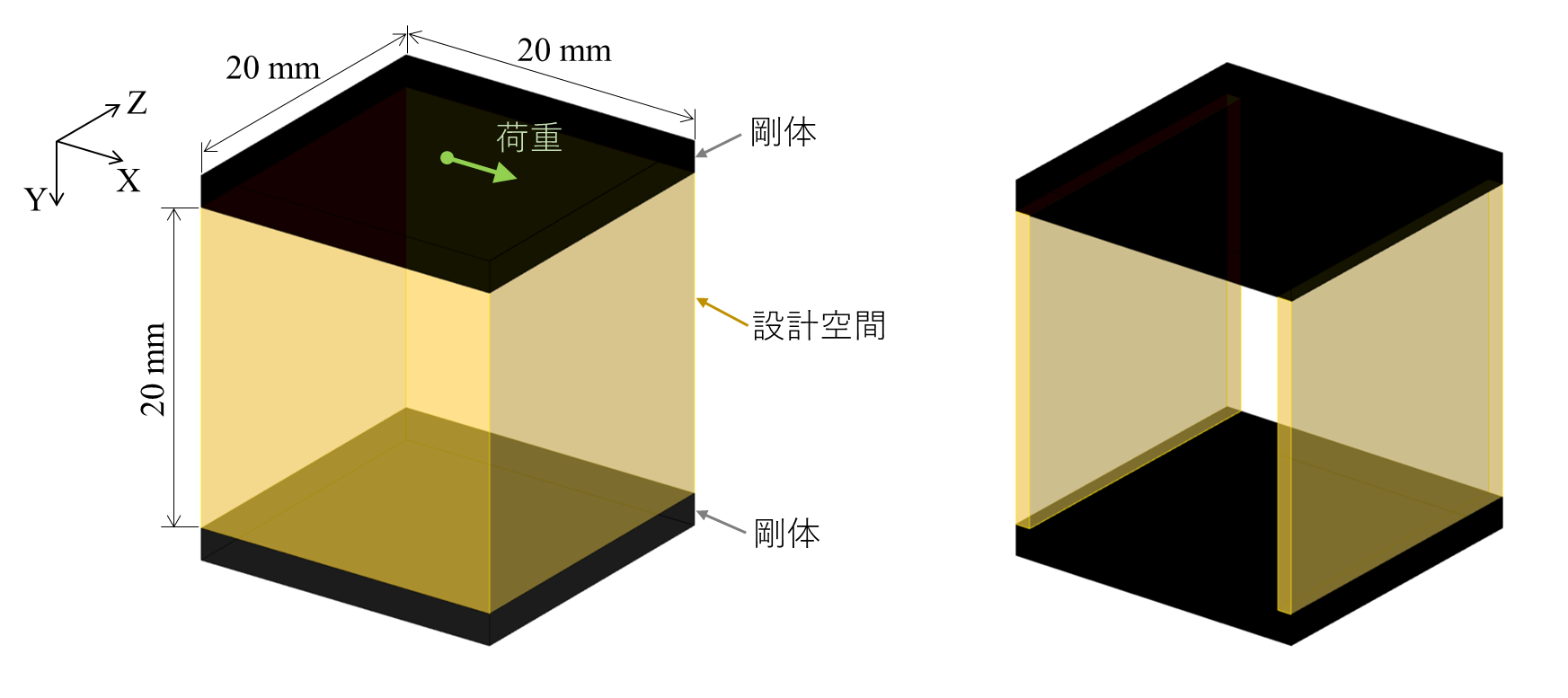
このとき,下の部品に対して上の部品をX方向に並進運動させる(その他の方向に対しては変形量や回転量をできるだけ小さくする)構造が必要であるとします。すなわち,X方向の剛性を低くし,その他の方向に対しては剛性を高くする構造について考えます。
また,次の条件も考慮します。
- 製造容易性を考慮して2次元の押出形状とする。
- 梁の板厚は1 mmとする。
- 一体構造を想定し,材料はポリプロピレン樹脂(ヤング率2.0 GPa)のみを使用する。
片持ち梁の変形
まずは,一本の片持ち梁について考えます。本稿では簡単のためXY平面内の変形のみを考えることにします。
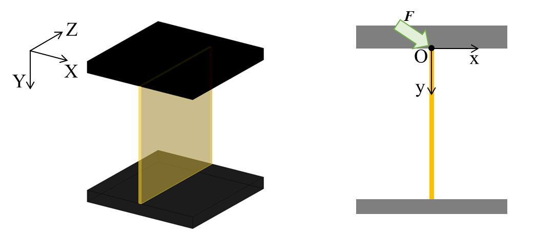
図のように,幅\(b\),板厚\(h\),長さ\(L\)の一様梁がY方向に配置されているとします。梁端部に荷重\(\boldsymbol W=[F_x, F_y, M_z]^T\)を与えたとき,微小変形状態における端部の変位と回転\(\boldsymbol T=[d_x, d_y, \theta_z]^T\)は次式で表されます。
\(\boldsymbol{T} = [S] \boldsymbol{W}\\
\begin{bmatrix} d_x \\ d_y \\ \theta_z \end{bmatrix}
=\begin{bmatrix} \frac{l^3}{3EI} & 0 & \frac{l^2}{2EI} \\
                0 & \frac{l}{Ebh} &  0  \\
                 \frac{l^2}{2EI} & 0 &  \frac{l}{EI}\end{bmatrix}
\begin{bmatrix} F_x \\ F_y \\ M_z \end{bmatrix}\)
ここで,\(E\)は材料ヤング率です。\(I\)は断面2次モーメントで,長方形断面の場合は次の式で表されます。
\(I = \frac{bh^3}{12}\)
\([S]\)はコンプライアンス行列で,荷重に対する変形のしやすさを表します。また,剛性行列\([Q]\)はコンプライアンス行列の逆行列として次式で与えられます。
\(\boldsymbol{W} = [Q]\boldsymbol{T}\\
\begin{bmatrix} F_x \\ F_y \\ M_z \end{bmatrix}
=\begin{bmatrix}  \frac{12EI}{l^3} & 0 & -\frac{6EI}{l^2} \\
                  0 & \frac{bh}{l} &  0  \\
                  -\frac{6EI}{l^2} & 0 & \frac{4EI}{l} \end{bmatrix}
\begin{bmatrix} d_x \\ d_y \\ \theta_z \end{bmatrix}\)
コンプライアンス行列または剛性行列を用いることで,変位量と荷重の片方からもう一方を求めることができます。
例えば,\(h = 1 \text{ mm}, b = 20 \text{ mm}, l = 20 \text{ mm}\)とし,角度を変えて1 N負荷した場合の変位絶対値\(| d_x|,| d_y|\)および回転量\(|\theta_z|\)は下のグラフのようになります。
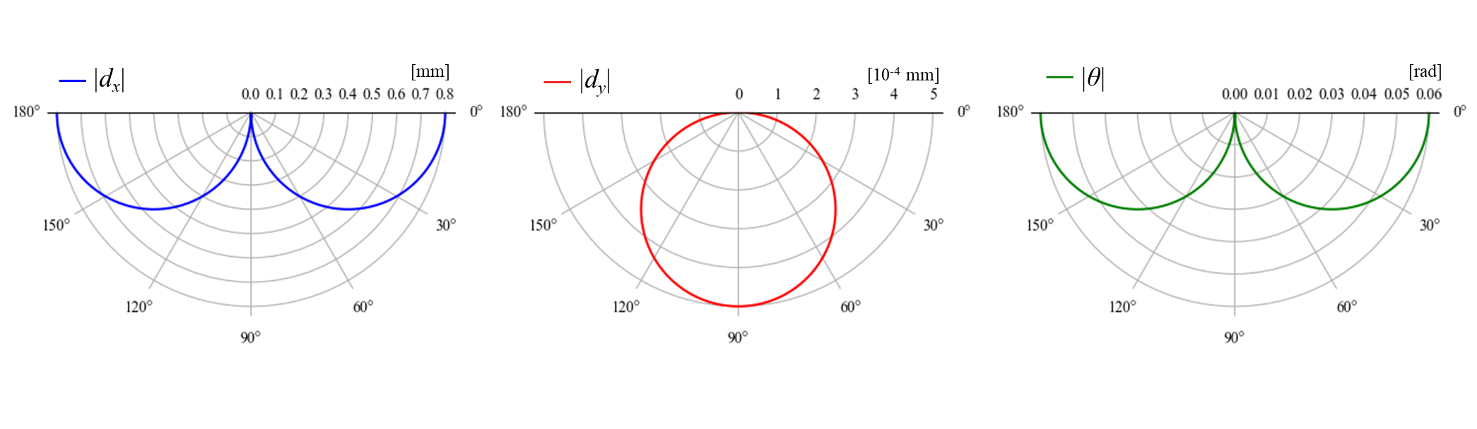
X方向の変位に比べてY方向の変位は非常に小さくなっています。このように,板厚に対して長さが十分大きい一様梁は長手方向に対する剛性が高く,板厚方向には低剛性であることが分かります。また,後述でスライダー構造と比較しますが,一様梁は回転に対しても低剛性になります。
上の計算ではX方向の荷重によって回転が生じています。モーメント荷重が負荷されていない一様梁では回転中心は\(y= {2 \over 3}l\)上になります。X方向の並進運動に近づけるには,回転中心をよりY方向に遠くする必要があります。逆方向へのモーメント荷重を負荷することで回転運動を生じさせないことも理論上可能ですが,実製品において荷重を厳密に制御することはあまり現実的ないので,構造特性を利用して並進運動を実現します。
梁位置の変更
次に,XY平面内で梁の接続位置や角度が異なる場合を考えます。
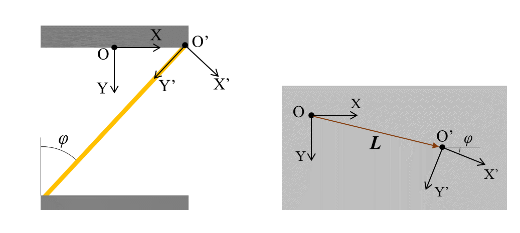
梁先端を原点とする座標系(\(\text O'\)とします)では,上記までと同じように変位-荷重関係が成立します。
\(\boldsymbol{W'} = [Q'] \boldsymbol{T'}\)
もとの座標系(\(\text O\)とします)における\(\text O’\)原点の位置ベクトルを\(\boldsymbol{L}=(L_x, L_y)\),角度を\(\phi\)とすると,\(\text O\)に荷重\(\boldsymbol W\)を負荷した際に\(\text O’\)に作用する荷重\(\boldsymbol W'\)は次のように表されます。
\(\begin{bmatrix} F_x' \\ F_y' \\ M_z' \end{bmatrix} =
\begin{bmatrix} \cos{\phi} & \sin{\phi} & 0 \\
                -\sin{\phi} & \cos{\phi} & 0 \\
                L_y & -L_x & 1 \end{bmatrix}
\begin{bmatrix} F_x \\ F_y \\ M_z \end{bmatrix}\\\)
ここで,\(\boldsymbol W'\)から\(\boldsymbol W\)への座標変換行列を\([N]\)とします。
\(\begin{bmatrix} F_x \\ F_y \\ M \end{bmatrix} =
\begin{bmatrix} \cos{\phi} & -\sin{\phi} & 0 \\
                \sin{\phi} & \cos{\phi} & 0 \\
                L_x\sin{\phi}-L_y\cos{\phi} & L_x\cos{\phi}+L_y\sin{\phi} & 1 \end{bmatrix}
\begin{bmatrix} F_x' \\ F_y' \\ M_z' \end{bmatrix} \\
\boldsymbol{W }= [N] \boldsymbol{W'}\)
このとき,X'方向およ向の単位ベクトルをそれぞれ\(\boldsymbol{n_{x'}}\)と\(\boldsymbol{n_{y'}}\)とすると,変換行列\([N]\)の3行目1つ目と2つ目の成分は次式で表されます。
\(N_{31} = (\boldsymbol{L}\times\boldsymbol{n_{x'}})\cdot \boldsymbol{e_3}\\
N_{32} = (\boldsymbol{L}\times\boldsymbol{n_{y'}})\cdot \boldsymbol{e_3}\\\)
また,同じ運動をする物体内で\(\text O\)の変位と\(\text O’\)の変位は次の関係式で表されます。
\(\begin{bmatrix} d_x' \\ d_y' \\ \theta_z' \end{bmatrix} =
\begin{bmatrix} \cos{\phi} & \sin{\phi} & L_x\sin{\phi}-L_y\cos{\phi}\\
                -\sin{\phi} & \cos{\phi} & L_x\cos{\phi}+L_y\sin{\phi} \\
                0 & 0 & 1 \end{bmatrix}
\begin{bmatrix} d_x \\  d_y \\ \theta_z \end{bmatrix} \\
\boldsymbol T' =[N]^\text T \boldsymbol T\)
これにより,\(\text{O}\)における荷重と変位および回転の関係は次の式となります。
\(\boldsymbol W = [N][Q'][N]^\text T \boldsymbol T\)
例えば,\(\boldsymbol L=(L_x,0)\)の位置に角度\(\phi = {\pi \over 4}\)で梁を配置した場合は,剛性行列\([Q]=[N][Q'][N]^\text T\)は次のようになります。
\([Q] =
\begin{bmatrix} {1 \over \sqrt{2}} & -{1 \over \sqrt{2}} & 0 \\
                {1 \over \sqrt{2}} & {1 \over \sqrt{2}} & 0 \\
                {1 \over \sqrt{2}}L_x & {1 \over \sqrt{2}}L_x & 1 \end{bmatrix}
\begin{bmatrix}  \frac{12EI}{l^3} & 0 & -\frac{6EI}{l^2} \\
                  0 & \frac{bh}{l} &  0  \\
                  -\frac{6EI}{l^2} & 0 & \frac{4EI}{l} \end{bmatrix}
\begin{bmatrix} {1 \over \sqrt{2}} & {1 \over \sqrt{2}} & {1 \over \sqrt{2}}L_x\\
                -{1 \over \sqrt{2}} & {1 \over \sqrt{2}} & {1 \over \sqrt{2}}L_x \\
                0 & 0 & 1 \end{bmatrix} \\
= \begin{bmatrix}
{6E \over l^3} + {l\over 2bh} & {6E \over l^3} - {l\over 2bh} & {-3\sqrt{2}E \over l^2}+{6EL_x \over l^3}+{lL_x \over 2bh}\\
& {6E \over l^3} + {l\over 2bh} & {-3\sqrt{2}E \over l^2}+{6EL_x \over l^3}-{lL_x \over 2bh}\\
\text{sym.} & &
{4E \over l} - {6\sqrt{2}EL_x \over l^2} + {6EL_x^2 \over l^3} + {l L_x^2 \over 2bh}
\end{bmatrix}\\\)
このとき,\(h = 1 \text{ mm}, b = 20 \text{ mm}, l = 20\sqrt{2} \text{ mm}, L_x=10 \text{ mm}\)とし,\(1\text{ N}\)の荷重を角度を変えて負荷した場合の変位絶対値\(|d_x|,| d_y|\)および回転量\(|\theta_z|\)は下のグラフのようになります。

単純な片持ち梁に比べると変位の値や最大となる荷重角度が異なります。このように梁の位置や方向を変えるだけで構造の特性を大きく変えることができます。
では,1本の梁だけで並進移動を実現するような構造はあり得るでしょうか。\(h = 1 \text{ mm}, b = 20 \text{ mm}\)として上記設計範囲内で上下部材をつなげるように梁を配置した場合,X方向に1 N負荷したときの挙動\(d_x, d_y, \theta_z\)の取りうる範囲は次のようになります。
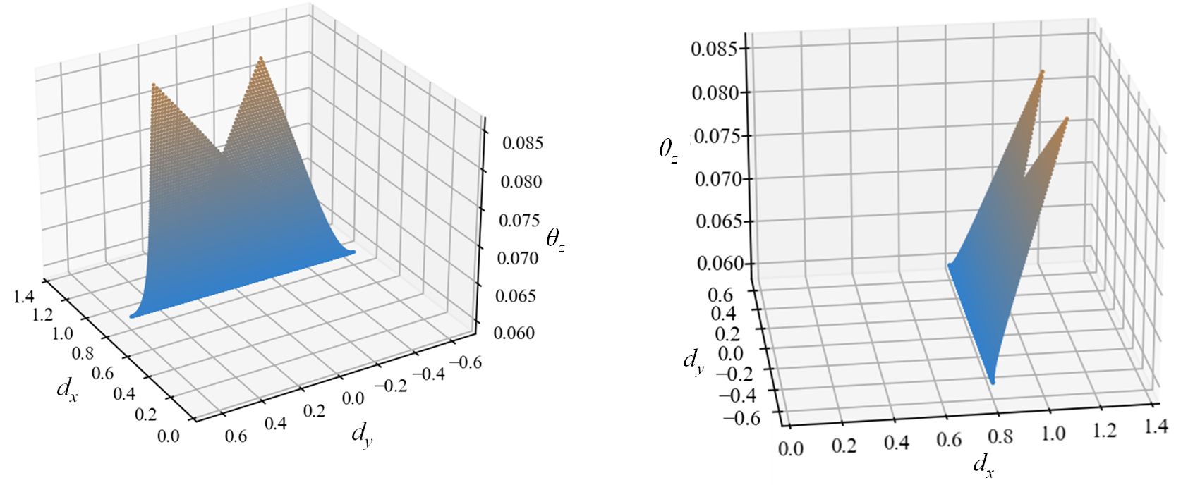
どの梁位置でも回転角\(\theta_z\)が生じ,1本の梁だけでは並進移動となる構造は実現できないことが分かります。
梁の直列,並列
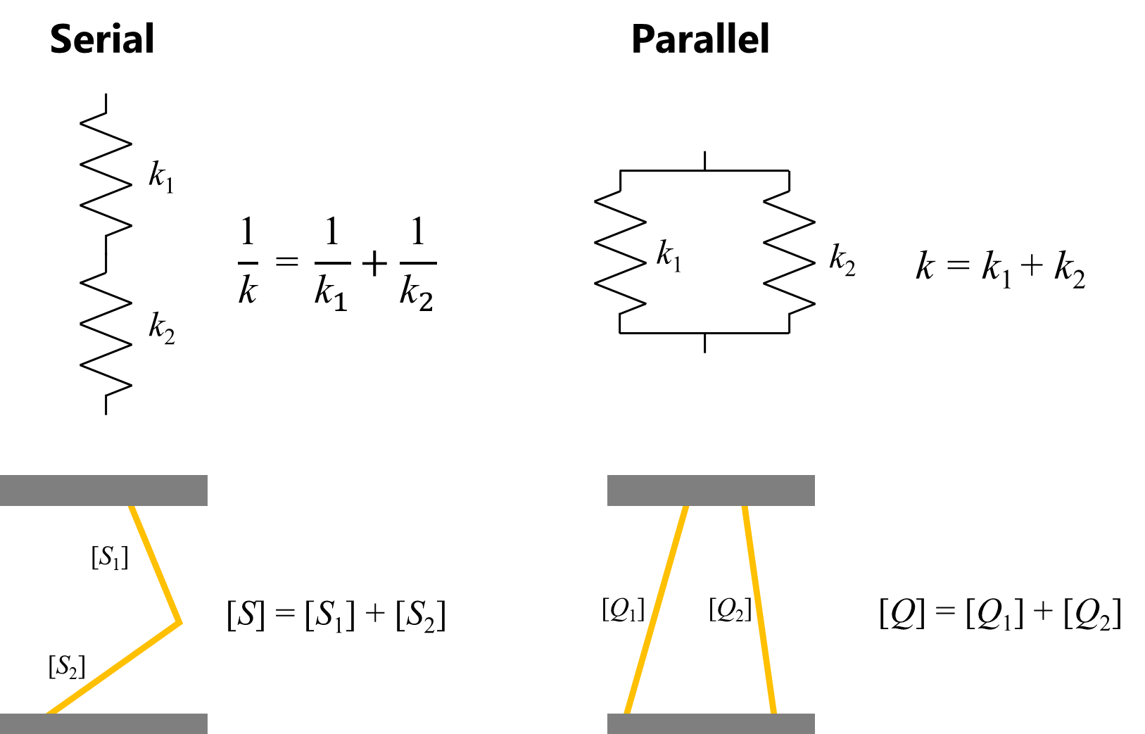
複数の梁で構造を構成することを考えます。梁を直列や並列にした際は,ばね定数と同じようにコンプライアンスや剛性の足し合わせで求められます。
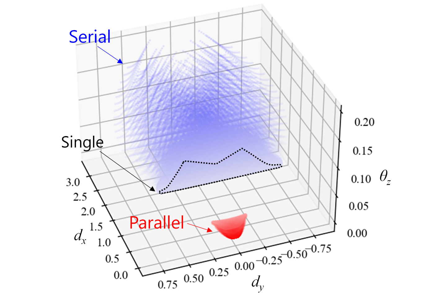
これらを用いて,梁が2本の場合に,X方向に1N負荷したときの変位および回転\(d_x, d_y, \theta_z\)の値を計算すると下図の等になります。青色のプロットは直列のケース,赤色のプロットは並列のケースを示しており,それぞれ約40万点ほどをプロットしています。黒点線で示す部分は,上で示した梁が一本の場合に取りうる領域であり,直列のケースに含まれます。また,並列のケースでは梁同士が交わるケースはプロットしていません。
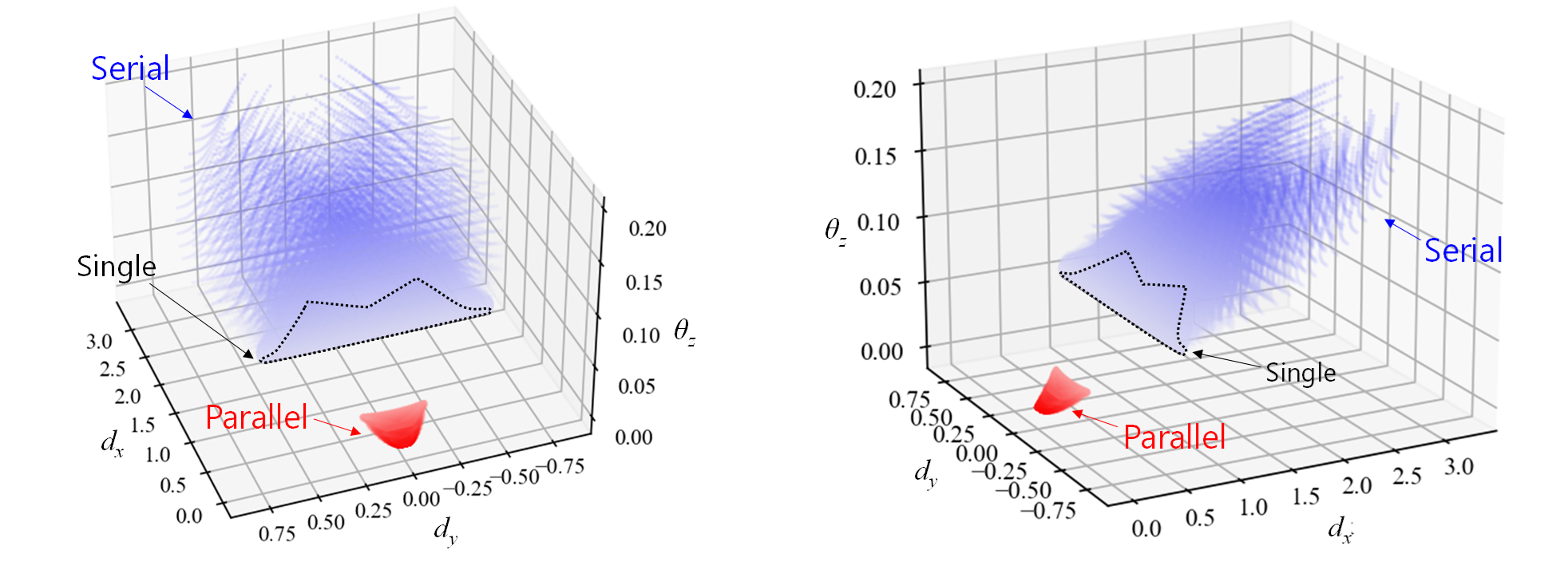
直列では梁は柔らかくなり,X方向変位とともに回転量も増加しています。回転量を小さくするには並列につなぐ必要があることが分かります。
スライダー構造の剛性
前置きが長くなりましたが,スライダー構造の挙動を導出します。スライダー構造は平行な梁を並列にしています。2つの梁先端の位置ベクトルを\((L_{x1},0)\)と\((L_{x2},0)\)とすると,剛性行列は次のようになります。
\([Q] = \begin{bmatrix}
\frac{24EI}{l^3} & 0 & \frac{12EI}{l^3}(L_{x1}+L_{x2}-l)\\
0 & \frac{2bh}{l} &  0  \\
\frac{12EI}{l^3}(L_{x1}+L_{x2}-l) & 0 &
\frac{12EI}{l^3}(L_{x1}^2+L_{x2}^2-L_{x1}l-L_{x2}l)+ \frac{8EI}{l}\end{bmatrix}\)
ここで,\(L_{x1}=-L_{x2}=L\)とすると,
\([Q] = \begin{bmatrix}
\frac{24EI}{l^3} & 0 & -\frac{12EI}{l^2}\\
0 & \frac{2bh}{l} &  0  \\
-\frac{12EI}{l^2} & 0 & \frac{24EI}{l^3}L^2 + \frac{8EI}{l}\end{bmatrix}\)
となります。回転に対する対角成分\(Q_{33}\)以外の成分は片持ち梁の2倍となっていますが,\(Q_{33}\)には\(L\)の2乗に比例する項が追加されています。このことから,片持ち梁の回転に対する剛性が高くなった(自由度拘束が追加された)ことが分かります。また,モーメント荷重が作用しないときの回転中心は\(y= {2 \over 3}l+{2 L^2\over l}\)上となり(興味のある方は計算してみてください),\(L\)を大きくするほど並進運動に近くなります。
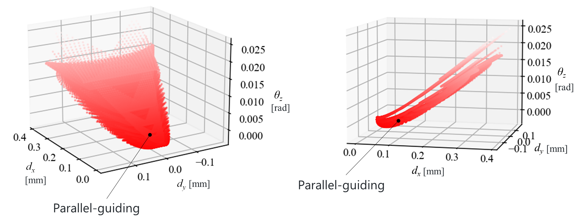
具体的に,\(h = 1 \text{ mm}, b = 20 \text{ mm}, l = 20 \text{ mm}\)とし,\(\pm 10 \text{ mm}\)の位置に梁を平行配置したときの挙動を見てみます。X方向に1N負荷したときの変位および回転\(d_x, d_y, \theta_z\)の値は下図に位置します。
角度を変えて1N負荷した際の挙動は次のようになります。回転角のスケールのみが片持ち梁で示した図と異なります。X,Y方向変位のみ同時に片持ち梁の挙動を点線で示します。
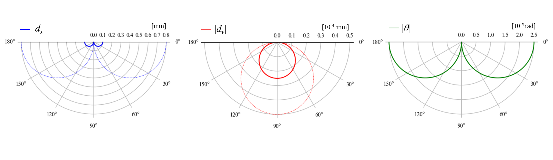
片持ち梁の場合と比較して,回転量が大幅に小さくなっていることが分かります。このようにスライダー構造では,一方向以外の剛性を大きくするように梁を配置しており,それにより並進移動が誘導されます。
スライダ構造では,2本の梁を並列に繋げたことで片持ち梁に比べて剛性が高くなります。方向荷重をかけた際のY方向変位は,片持ち梁と比較し断面積に反比例して1/2となります。一方で,回転に対する剛性が高くなったことでX方向の変位は約1/8程度となっています。
変形を誘導したいX方向の剛性をより小さくしたい場合はどのような構造にすべきでしょうか。これについては次回の記事で紹介します。
まとめ
簡単な材料力学と剛体力学を用いて,剛性異方性のあるスライダ構造を例に,コンプライアントメカニズムの変形挙動を計算する方法について紹介しました。
次の記事では,より異方性を顕著にするための方法とその際の課題について紹介します。
Introduction
In compliant mechanisms and mechanical metamaterials that utilize elastic deformation, deformation in unintended directions may be unfavorable. Therefore, they are required to have sufficient stiffness in directions where deformation is not desired. Compliant mechanisms are designed on the basis with stiffness anisotropy. In this article, we will discuss structures with anisotropic macroscopic stiffness not material anisotropy.
In order to design a structure with the expected deformation behaviors, it is important to understand the stiffness in each direction, in other words, the relationship between the deformation and the applied load. Although this relationship can be calculated using the finite element method, it is important to use a simplified model to reduce calculation time in order to perform many trials for optimization. This article introduces a simple calculation method for compliant mechanism behavior that utilizes basic material mechanics and rigid body mechanics.
Slider structure
One of the structures frequently used as a component of compliant mechanisms is a structure called a slider structure (parallel-guiding mechanism). As described in previous article, this structure is rigid against deformations other than unidirectional and induces translational movement. Although this structure can be derived from the concept of constraining the deformation degrees of freedom, I would like to explain the stiffness characteristics using mathematical formulas in this article.
Setting up the problem
Set the following conditions for considering the structure. In this case, we consider a structure that connects upper and lower rigid parts in a 20 mm cubic design space.
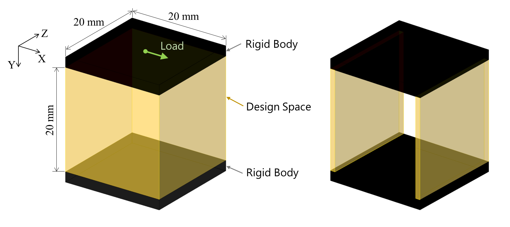
Let us assume that we need a structure that allows the upper part to translate in the x-direction relative to the lower part (and minimize the amount of deformation and rotation in other directions as much as possible). In other words, we consider a structure with low stiffness in the X direction and high stiffness in the other directions.
We also consider the following conditions
- The beam should be a 2-dimensional extruded shape for ease of fabrication.
- The thickness of the beam should be 1 mm.
- Assuming a one-piece structure, only polypropylene resin (Young's modulus 2.0 GPa) should be used as material.
Deformation of a cantilever beam
First, we consider a single cantilever beam. For simplicity, we will only consider deformations in the XY plane.
Suppose a uniform beam of width \(b\), thickness \(h\), and length \(L\) is placed in the Y direction as shown in the figure. When a load \(\boldsymbol W=[F_x, F_y, M_z]^T\) is applied to the end of the beam, the displacement and rotation \(\boldsymbol T=[d_x, d_y, \theta_z]^T\) of the end in the infinitesimal deformation state are expressed as follows
\(\boldsymbol{T} = [S] \boldsymbol{W}\\
\begin{bmatrix} d_x \\ d_y \\ \theta_z \end{bmatrix}
=\begin{bmatrix} \frac{l^3}{3EI} & 0 & \frac{l^2}{2EI} \\
                0 & \frac{l}{Ebh} &  0  \\
                 \frac{l^2}{2EI} & 0 &  \frac{l}{EI}\end{bmatrix}
\begin{bmatrix} F_x \\ F_y \\ M_z \end{bmatrix}\)
where \(E\) is the Young's modulus of the material. \(I\) is the sectional second moment, which for a rectangular section is expressed by the following equation
\(I = \frac{bh^3}{12}\)
The \([S]\) is the compliance matrix, which represents the ease of deformation with respect to the load. Also, the stiffness matrix \([Q]\) is the inverse of the compliance matrix and is given by
\(\boldsymbol{W} = [Q]\boldsymbol{T}\\
\begin{bmatrix} F_x \\ F_y \\ M_z \end{bmatrix}
=\begin{bmatrix}  \frac{12EI}{l^3} & 0 & -\frac{6EI}{l^2} \\
                  0 & \frac{bh}{l} &  0  \\
                  -\frac{6EI}{l^2} & 0 & \frac{4EI}{l} \end{bmatrix}
\begin{bmatrix} d_x \\ d_y \\ \theta_z \end{bmatrix}\)
The compliance or stiffness matrix can be used to obtain one of the motion and loads from the other.
For example, if \(h = 1 \text{ mm}, b = 20 \text{ mm}, l = 20 \text{ mm}\) and 1 N load is applied at different angles, the absolute translation \(|d_x|, |d_y|\) and rotation \(|\theta_z|\) are shown in the graph below.
The displacement in the y-direction is very small compared to the translation in the x-direction. Thus, it can be seen that a uniform beam with a sufficiently large length relative to the thickness has high stiffness in the longitudinal direction and low stiffness in the thickness direction. Also, uniform beams are less stiff against rotation, as we will compare with slider structures below.
In the above calculation, the rotation is caused by a load in the x-direction. For an unloaded uniform beam, the center of rotation is on \(y= {2 \over 3}l\). To approach translational motion in the x direction, the center of rotation must be farther away in the y direction. Theoretically, it is possible to prevent rotational motion by applying a moment load in the opposite direction, but it is not feasible to strictly control the load in a real product, so translational motion is achieved by utilizing the structural characteristics.
Changing beam positions
Next, consider the case where the beams are connected at different positions and angles in the XY plane.
In a coordinate system with the origin at the beam tip (let \(\text O'\)), the displacement-load relationship holds as before above.
\(\boldsymbol{W'} = [Q'] \boldsymbol{T'}\)
If the position vector of the \(\text O'\) origin in the original coordinate system (let \(\text O\)) is \(\boldsymbol{L}=(L_x, L_y)\) and the angle is \(\phi\), then when the load \(\text O\) is applied to \(\boldsymbol W\), the load \(\boldsymbol W'\) acting on \(\text O'\) when loaded with \(W\) is expressed as follows.
\(\begin{bmatrix} F_x' \\ F_y' \\ M_z' \end{bmatrix} =
\begin{bmatrix} \cos{\phi} & \sin{\phi} & 0 \\
                -\sin{\phi} & \cos{\phi} & 0 \\
                L_y & -L_x & 1 \end{bmatrix}
\begin{bmatrix} F_x \\ F_y \\ M_z \end{bmatrix}\\\)
Let '$[N]$' be the coordinate transformation matrix from \(\boldsymbol W'\) to \(\boldsymbol W\).
\(\begin{bmatrix} F_x \\ F_y \\ M \end{bmatrix} =
\begin{bmatrix} \cos{\phi} & -\sin{\phi} & 0 \\
                \sin{\phi} & \cos{\phi} & 0 \\
                L_x\sin{\phi}-L_y\cos{\phi} & L_x\cos{\phi}+L_y\sin{\phi} & 1 \end{bmatrix}
\begin{bmatrix} F_x' \\ F_y' \\ M_z' \end{bmatrix} \\
\boldsymbol{W }= [N] \boldsymbol{W'}\)
In this case, if the unit vectors in the X'-direction and \(\boldsymbol{n_{x'}}\) and \(\boldsymbol{n_{y'}}\) are respectively, the first and second components of the third row of the transformation matrix \([N]\) are expressed as follows.
\(N_{31} = (\boldsymbol{L}\times\boldsymbol{n_{x'}})\cdot \boldsymbol{e_3}\\
N_{32} = (\boldsymbol{L}\times\boldsymbol{n_{y'}})\cdot \boldsymbol{e_3}\\\)
Also, the displacement of \(\text O\) and the displacement of \(\text O'\) within the same object in motion can be expressed by the following relation.
\(\begin{bmatrix} F_x' \\ F_y' \\ M_z' \end{bmatrix} =
\begin{bmatrix} \cos{\phi} & \sin{\phi} & 0 \\
                -\sin{\phi} & \cos{\phi} & 0 \\
                L_y & -L_x & 1 \end{bmatrix}
\begin{bmatrix} F_x \\ F_y \\ M_z \end{bmatrix}\\\)
The relationship between load, displacement, and rotation in `\(\text{O}\) is then given by the following equation
\(\boldsymbol W = [N][Q'][N]^\text T \boldsymbol T\)
For example, if the beam is placed at \(\boldsymbol L=(L_x,0)\) with angle \(\phi = {\pi \over 4}\), the stiffness matrix \([Q]=[N][Q'][N]^\text T\) will be as follows.
\([Q] =
\begin{bmatrix} {1 \over \sqrt{2}} & -{1 \over \sqrt{2}} & 0 \\
                {1 \over \sqrt{2}} & {1 \over \sqrt{2}} & 0 \\
                {1 \over \sqrt{2}}L_x & {1 \over \sqrt{2}}L_x & 1 \end{bmatrix}
\begin{bmatrix}  \frac{12EI}{l^3} & 0 & -\frac{6EI}{l^2} \\
                  0 & \frac{bh}{l} &  0  \\
                  -\frac{6EI}{l^2} & 0 & \frac{4EI}{l} \end{bmatrix}
\begin{bmatrix} {1 \over \sqrt{2}} & {1 \over \sqrt{2}} & {1 \over \sqrt{2}}L_x\\
                -{1 \over \sqrt{2}} & {1 \over \sqrt{2}} & {1 \over \sqrt{2}}L_x \\
                0 & 0 & 1 \end{bmatrix} \\
= \begin{bmatrix}
{6E \over l^3} + {l\over 2bh} & {6E \over l^3} - {l\over 2bh} & {-3\sqrt{2}E \over l^2}+{6EL_x \over l^3}+{lL_x \over 2bh}\\
& {6E \over l^3} + {l\over 2bh} & {-3\sqrt{2}E \over l^2}+{6EL_x \over l^3}-{lL_x \over 2bh}\\
\text{sym.} & &
{4E \over l} - {6\sqrt{2}EL_x \over l^2} + {6EL_x^2 \over l^3} + {l L_x^2 \over 2bh}
\end{bmatrix}\\\)
In this case, \(h = 1 \text{ mm}, b = 20 \text{ mm}, l = 20\sqrt{2} \text{ mm}, L_x=10 \text{ mm}\) and the absolute value of displacement \(|d_x|,| d_y|\) when \(1\text{ N}\) load is applied with different angle and The amount of rotation \(|theta_z|\) is as shown in the graph below.
Compared to a simple cantilever beam, the translation values and the maximum load angle are different. Thus, simply by changing the position and orientation of the beams, the properties of the structure can be significantly altered.
Then, is it possible to have a structure that achieves translational movement with only one beam? If the beams are placed to connect the upper and lower members within the above design range with \(h = 1 \text{ mm}, b = 20 \text{ mm}\), the possible range of behavior \(d_x, d_y, \theta_z\) under 1 N load in the X direction is as follows.
It can be seen that at any beam position, a rotation angle \(\theta_z\) occurs, and that the structure cannot be realized as a translational movement with only one beam.
Series and parallel beams
Consider a structure with multiple beams. When beams are in series or parallel, compliance and stiffness are obtained by adding up the compliance and stiffness, just like spring constants.
Using these, the values of translation and rotation \(d_x, d_y, \theta_z\) are calculated for the case of two beams with 1N force in the x-direction, as shown in the figure below. The blue plot shows the series case and the red plot shows the parallel case, each plotting approximately 400,000 points. The black dotted line indicates the area that can be taken in the case of a single beam, which is included in the series case. The parallel case does not include the case where the beams intersect each other.
In the series case, the beams are softer and the amount of rotation increases along with the displacement in the x-direction. It can be seen that the beams need to be connected in parallel in order to reduce the rotation.
Stiffness of slider structure
Having said all that up front, let's derive the behavior of a slider structure. The slider structure consists of parallel beams, and if the position vectors of the two beam tips are \((L_{x1},0)\) and \((L_{x2},0)\), the stiffness matrix is as follows
\([Q] = \begin{bmatrix}
\frac{24EI}{l^3} & 0 & \frac{12EI}{l^3}(L_{x1}+L_{x2}-l)\\
0 & \frac{2bh}{l} &  0  \\
\frac{12EI}{l^3}(L_{x1}+L_{x2}-l) & 0 &
\frac{12EI}{l^3}(L_{x1}^2+L_{x2}^2-L_{x1}l-L_{x2}l)+ \frac{8EI}{l}\end{bmatrix}\)
Let \(L_{x1}=-L_{x2}=L\) , then
\([Q] = \begin{bmatrix}
\frac{24EI}{l^3} & 0 & -\frac{12EI}{l^2}\\
0 & \frac{2bh}{l} & 0 \\
-\frac{12EI}{l^2} & 0 & \frac{24EI}{l^3}L^2 + \frac{8EI}{l}\end{bmatrix}\)
Components are twice that of the cantilever beam, except for the diagonal components to the rotation \(Q_{33}\) has an additional term proportional to the square of \(L\). This indicates that the cantilever beam is now stiffer against rotation (additional degrees-of-freedom constraint). Also, the center of rotation when no moment load is acting is on \(y= {2 \over 3}l+{2 L^2\over l}\) (you can do the calculation if you are interested), and the larger \(L\) is, the closer to translational motion it is.
Specifically, let \(h = 1 \text{ mm}, b = 20 \text{ mm}, l = 20 \text{ mm}\) and let us look at the behavior of a beam placed parallel to the beam at \(\pm10 \text{ mm}\). The translation and rotation \(d_x, d_y, \theta _z\) values are located in the figure below.
The behavior of a 1N load at different angles is shown below. Only the scale of the rotation angle differs from the figure shown for the cantilever. The displacements in X and Y direction of the cantilever beam show with dotted lines.
It can be seen that the rotation is much smaller than in the cantilever beam case. Thus, in the slider structure, the beams are arranged to increase the stiffness in all but one direction, thereby inducing translational movement.
In the slider structure, two beams are connected in parallel, which makes it stiffer than a cantilever beam. The displacement in the y-direction under a load in the x-direction is inversely proportional to the cross-sectional area, which is 1/2 of that of a cantilever beam. On the other hand, the displacement in the X direction is about 1/8 due to the higher rigidity against rotation.
How should the structure be designed if we want to reduce the stiffness in the X direction more? This will be discussed in the next article.
Summary
Using simple material mechanics and rigid body mechanics, we have shown how to compute the deformation behavior of compliant mechanisms using a slider structure with stiffness anisotropy as an example.
In the next article, we will show how to make the anisotropy more pronounced and the challenges in doing so.
