
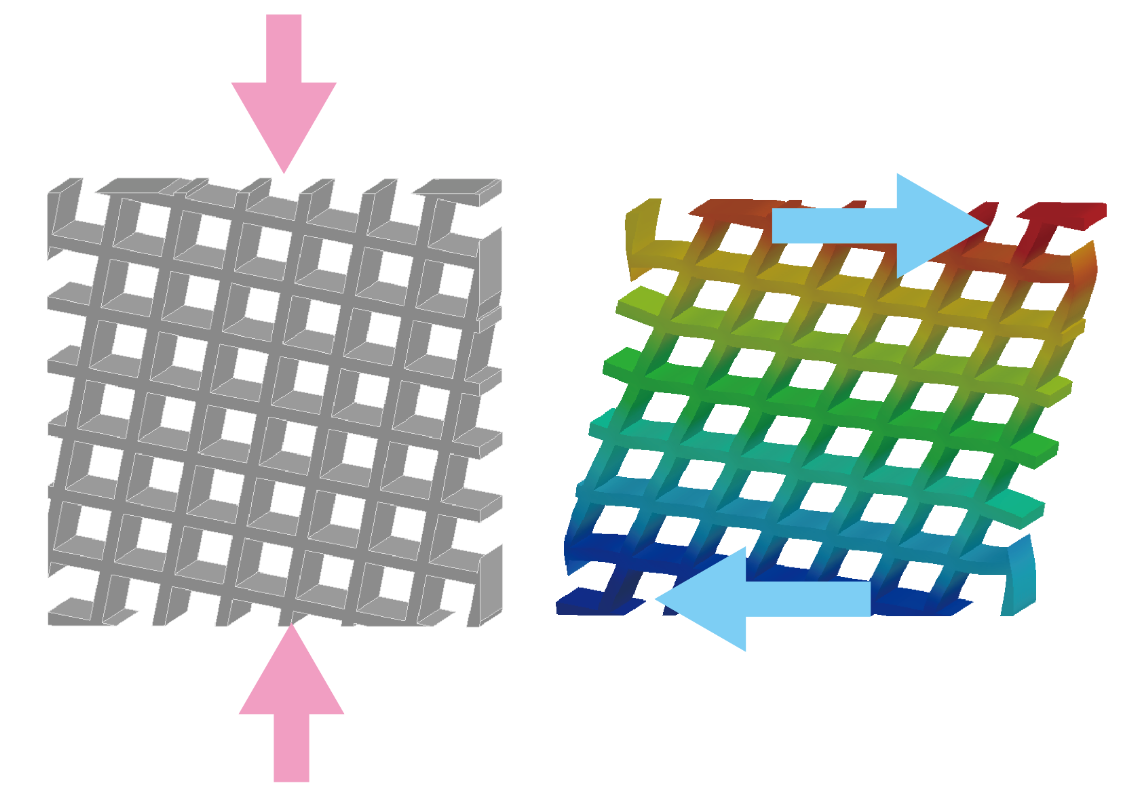
概要
ミッドソールに3Dプリントされた特殊な構造が埋め込まれたアディダスのシューズ「4DFWD」は踏み込み力を推進力に変換する機能を持ちます。本記事ではこの機能を圧縮をせん断に変換するメカニカルメタマテリアルとして解釈し、その設計方法を解説します。
本記事は以下の3部構成のうち2つ目について解説します。
(2) 圧縮をせん断に変換するメカニカルメタマテリアルの設計
(3) 踏み込み力を推進力に変換するミッドソールの設計
圧縮応力をせん断ひずみに変換する材料物性値\(S_{32}\)
前回の記事では圧縮応力がせん断ひずみに変換される材料物性を2次元線形弾性構成則の観点から説明し、それはコンプライアンス行列\(\mathbf{S}(\theta)\)の\((3,2)\)成分\(S(\theta)_{32}\)であることを明らかにしました。この値は材料の回転角度\(\theta\)を用いて以下のようにあらわされました。
\(S(\theta)_{32} = \sin{4\theta}\cdot\frac{1}{4}\left(\frac{1}{G} - \frac{2(1+\nu)}{E}\right) = S(\theta)_{ang} \times S_{mat}\tag{1-1}\)
ここで\(S(\theta)_{32}\)は回転角に関する項\(S(\theta)_{ang}\)と材料特性に関する項\(S_{mat}\)に分離されました。
\(S(\theta)_{ang} = \sin{4\theta}, \quad S_{mat} = \frac{1}{4}\left(\frac{1}{G} - \frac{2(1+\nu)}{E}\right)\tag{1-2}\)
よって\(S(\theta)_{32}\)の最大化は回転角度・材料特性それぞれ独立に行うことができます。
\(S(\theta)_{ang}\)の最大化
\(S(\theta)_{ang}\)の最大化は簡単で、回転角\(\theta\)が\(22.5^\circ\)の時最大値\(1\)を取ります。よってこのとき\(S(\theta)_{32}=S_{mat}\)が成り立ちます。
\(S_{mat}\)の最大化
等方材料であるとき、この値は0となります。この値の絶対値を大きくするためには、ヤング率\(E\)とせん断率\(G\)の比が大きく、または小さくする必要があります。すなわち
\(E>>G, \quad \text{or} \quad E<
であるときに圧縮応力がせん断ひずみに大きく変換されます。
それではそのような材料物性を持つユニットセルはどのようなものが考えられるでしょうか?
以下では
- ヤング率\(E\)が低くせん断率\(G\)が高いXラティス
- ヤング率\(E\)が高くせん断率\(G\)が低い+ラティス
の2例を紹介します。
ユニットセルの均質化
それぞれのラティスを紹介する前に、まずラティスを均質な材料とみなしたときの等価なコンプライアンス行列\(S\)の計算方法である均質化法[1][2]をざっくり紹介します。
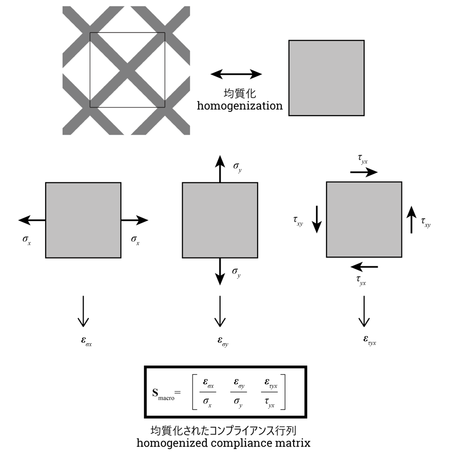
均質化法は以下のように周期構造であるラティスのユニットセルを取り出し、それを均質な材料として捉える手法です。
そのマクロコンプライアンス行列\(\mathbf{S}_{macro}\)は下図のようにユニットセルにそれぞれマクロ応力\(\sigma_x, \sigma_y, \gamma_{xy}\)を与え、
対応するマクロひずみ\(\boldsymbol\varepsilon_{\sigma_x}, \boldsymbol\varepsilon_{\sigma_y}, \boldsymbol\varepsilon_{\gamma_xy}\)を計算します。
このときユニットセルの境界面には周期境界条件を付与し、周期的な変形をするように拘束します。
そしてそれらを以下のように並べることでマクロコンプライアンス行列を求めます。
\(\mathbf{S}_{macro}=
\left[
\frac{\boldsymbol\varepsilon_{\sigma_x}}{\sigma_x} \quad
\frac{\boldsymbol\varepsilon_{\sigma_y}}{\sigma_y} \quad
\frac{\boldsymbol\varepsilon_{\gamma_{xy}}}{\gamma_{xy}}
\right]
\tag{2-1}\)
こうして求めたマクロコンプライアンス行列からマクロヤング率\(E_{macro}\)、マクロせん断率\(G_{macro}\)、マクロポアソン比\(\nu_{macro}\)を求めます。
今回は形状がXZ平面とYZ平面での鏡映対称性、90°回転対称性があるためマクロ線形弾性材料は正方異方性のクラスに分類されることから、以下のように求めることができます。
\(E_{macro}=\frac{1}{S_{macro,11}},\quad G_{macro}=\frac{1}{S_{macro,33}},\quad \nu_{macro}=-\frac{S_{macro,12}}{S_{macro,11}}
\tag{2-2}\)
ヤング率\(E\)が低くせん断率\(G\)が高いXラティス
それでは具体的なラティスのマクロ物性値を均質化法を用いて計測していきます。
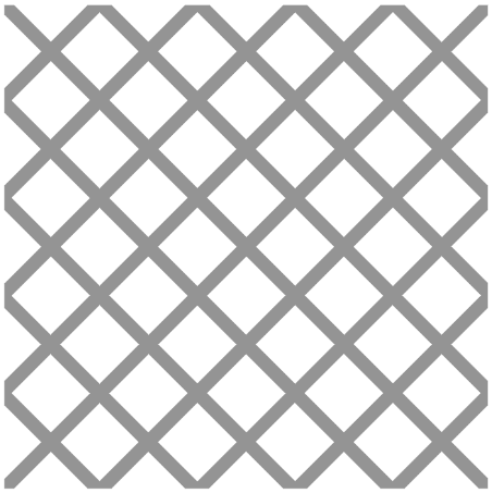
上図のようなXを敷き詰めたような格子構造(以下Xラティス)は
- 引張圧縮力に対して梁の曲げで変形し
- せん断力に対して梁の軸力で耐える
ため、ユニットセルの材料物性は
- マクロヤング率\(E_{macro}\):低
- マクロせん断率\(G_{macro}\):高
となると予想されます。
Carbon社の光造形用樹脂EPU40
ヤング率:\(8\text{[MPa]}\)
ポアソン比:0.5
を想定し
ユニットサイズを\(10/\sqrt{2}\text{[mm]}\)、板厚を\(1\text{[mm]}\)とした場合このユニットセルのマクロ材料物性を均質化法を用いて実際に計測したところ
- \(E_{macro}=0.210\text{[MPa]}\)
- \(G_{macro}=0.904\text{[MPa]}\)
- \(\nu_{macro}=0.890\)
となりました。予想通りマクロヤング率に対してマクロせん断率が高くなりました。また、面白いことにマクロポアソン比が約0.9と通常の材料と比較して非常に高い値を示しました。\(S_{mat}\)は式\(\text{(1-2)}\)から以下となりました。
\(S_{mat} = -4.22\text{[1/MPa]} \tag{3-1}\)
例えば\(\theta=22.5°\)で回転させると
\(S(\theta)_{32}=1.0\times(-4.22)=-4.22 \tag{3-2}\)
となり、また前回記事式\(\text{(2-1)}\)より以下のように圧縮力を正の向きのせん断変形に変換することがわかります。
\(\gamma_{xy} = S(\theta)_{32}\times(-\sigma_y)=4.22\sigma_y \tag{3-3}\)
ヤング率\(E\)が高くせん断率\(G\)が低い+ラティス
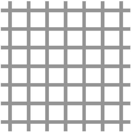
上図のような+を敷き詰めたような格子構造(以下+格子構造)は
- 引張圧縮力に対して梁の軸力で耐え
- せん断力に対して梁の曲げで変形する
ため、ユニットセルの材料物性は
- マクロヤング率\(E_{macro}\):低
- マクロせん断率\(G_{macro}\):高
となると予想されます。
同様にEPU40を用いてときの
ユニットサイズを\(5\text{[mm]}\)、板厚を\(1\text{[mm]}\)とした場合このユニットセルのマクロ材料物性を均質化法を用いて実際に計測したところ
- \(E_{macro}=1.854\text{[MPa]}\)
- \(G_{macro}=0.055\text{[MPa]}\)
- \(\nu_{macro}=0.027\)
となりました。予想通りマクロヤング率に対してマクロせん断率が低くなりました。また、面白いことにマクロポアソン比が約0とコルク材料のような低い値を示しました。\(S_{mat}\)は式\(\text{(1-2)}\)から以下となりました。
\(S_{mat} = 4.29\text{[1/MPa]} \tag{3-4}\)
例えば\(\theta=22.5°\)で回転させると
\(S(\theta)_{32}=1.0\times(4.29)=4.29 \tag{3-5}\)
となり、また前回記事式\(\text{(2-1)}\)より以下のように圧縮力を負の向きのせん断変形に変換することがわかります。
\(\gamma_{xy} = S(\theta)_{32}\times(-\sigma_y)=-4.29\sigma_y \tag{3-6}\)
式\(\text{(3-3)}\)と比較すると符号が逆転して大きさはほぼ同じであることがわかります。
よってXラティスと+ラティスの間には何かしらの関係性があると推察されます。
Xラティスと+ラティスの関係性
上で紹介した2つのラティスは、実は45°回転させるとぴったり重なり、同じラティスであるということができます。
当然ながらマクロコンプライアンス行列も45°回転させるとほぼ一致します。
また、Xラティスと+ラティスをそれぞれ22.5°回転させたラティスは下図のようになり、鏡映対称の関係となっています。
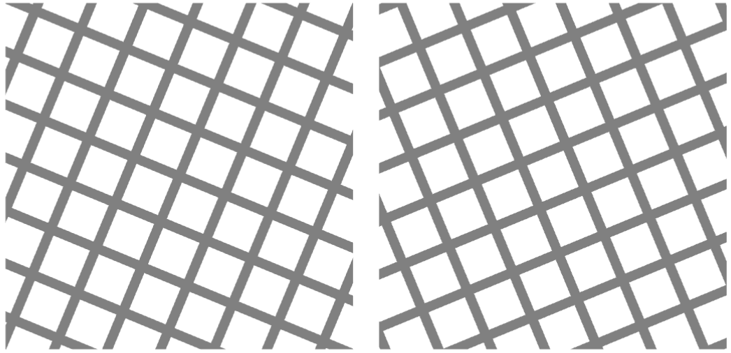
よってXラティス・+ラティスの圧縮-せん断成分\(S(\theta)_{32}\)が式\(\text{(3-2)}, \text{(3-5)}\)よりそれぞれ符号が逆転して大きさが同じである理由がこの幾何学的な対称性によることがわかります。
数値シミュレーションによる変形特性の確認
セットアップ
実際に圧縮力がせん断変形に変換されるか、数値シミュレーションを用いて確かめます。
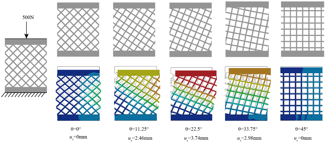
対象形状はXラティスとし、上面と下面に剛体ブロックを接続、下面固定、上面に下向き500Nの力をかけ、上面が横変位\(u_x\)を計測します。解析手法は簡易的に線形静解析としています。
回転角度は\(\theta = 0^\circ, 11.25^\circ, 22.5^\circ, 33.75^\circ, 45^\circ\)としました。
\(\theta=45^\circ\)のとき、+ラティスと同一形状となります。
結果
\(\theta=0^\circ, 45^\circ\)のとき\(u_x=0\text{[mm]}\)、\(\theta=11.25^\circ, 22.5^\circ, 33.75^\circ\)のとき、横変位が発生し、計算通り\(\theta=22.5^\circ\)の時、最大の値\(u_x=3.74\text{[mm]}\)となりました。ここから圧縮力がせん断変形に変換されるメカニカルメタマテリアルを設計できたことがわかりました。
FDM3Dプリンタを用いた試作
試作
最後に実試作による実験をして、設計通りの挙動をするか確認してみましょう。
試験片はFDM(熱溶解積層方式)3Dプリンタを用いて造形します。
材料は大きく変形させたいので軟質材料のTPUを用います。
圧縮試験は荷重変位試験機を用いて行います。
結果
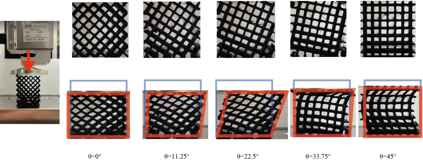
結果は上図のようになりました。
シミュレーション通り\(\theta=22.5^\circ\)の時に最も大きくせん断変形しました。
\(\theta=0^\circ, 11.25^\circ, 22.5^\circ\)では安定した変形を起こしていますが、
\(\theta=33.75^\circ, 45^\circ\)では圧縮力により座屈が起こってしまっています。
圧縮試験動画
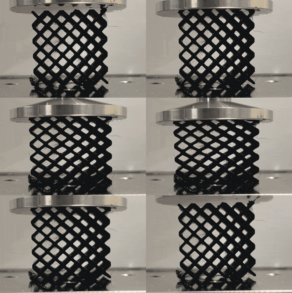
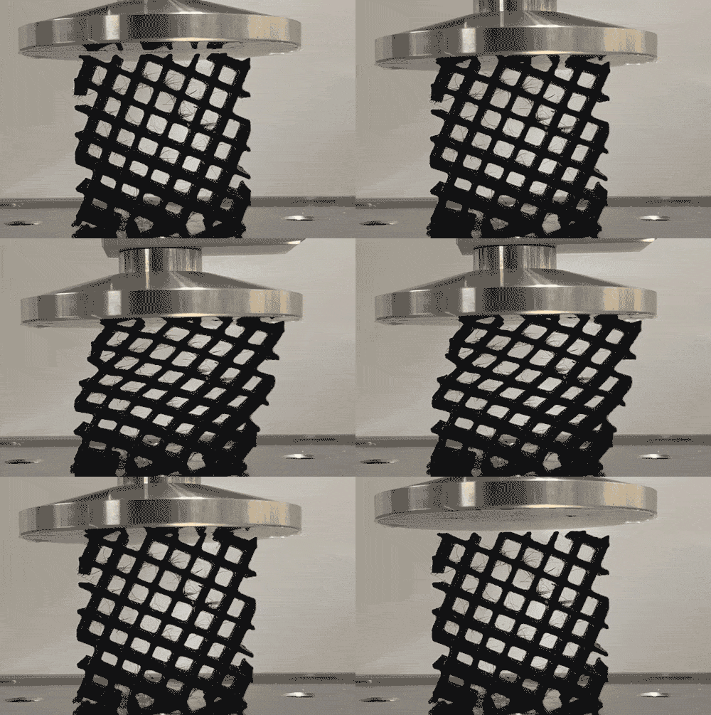
圧縮試験の動画でみると回転の有無でせん断変形が誘導されていることがよくわかります。
せん断変形時に上面が大きくスライドし、推進力を生みだしそうな変形となっていますね。
まとめ
圧縮力をせん断変形に変換するためには、ヤング率とせん断率の比が大きい特殊な材料を回転させれば良いことを材料力学の観点から明らかにしました。2つのラティス構造(Xラティス・+ラティス)について、均質化法を用いて等価なマクロ材料物性を計測し、上記性質を持つことを確認しました。また、Xラティスと+ラティスは回転させると一致することを幾何学的観点と材料力学的観点から理解しました。最後にシミュレーションと試作実験により、圧縮力がせん断変形に変換されるメカニカルメタマテリアルが設計できたことを確認しました。
次回は回転させたXラティスを用いて踏み込み力を推進力に変換するミッドソールを設計していきたいと思います。
参考文献
[1] 寺田 賢二郎, 均質化法を用いた複合材料の解析, 成形加工, 2017, 29 巻, 2 号, p. 42-46, 公開日 2020/09/10, Online ISSN 1883-7417, Print ISSN 0915-4027
[2] 寺田 賢二郎,平山 紀夫,山本 晃司,数値材料試験 有限要素法によるマルチスケール解析,丸善出版,2021,ISBN 978-4-621-30633-8
Overview
The adidas shoe "4DFWD," which has a special 3D-printed structure embedded in the midsole, has the function of converting stepping force into propulsive force. This article interprets this function as a mechanical metamaterial that converts compression into shear and explains how to design it.
This article explains the first of the following three parts.
(1) Explanation of macro physical properties that convert compression to shear
(2) Design of mechanical metamaterials that convert compression to shear
(3) Designing a midsole that converts stepping force into propulsive force
Material properties that convert compressive stress into shear strain \(S_{32}\).
In the previous article, we explained the material property that converts compressive stress into shear strain in terms of a two-dimensional linear elastic constitutive law, which is the \((3,2)\) component \(S(\theta)_{32}\) of the compliance matrix \(\mathbf{S}(\theta)\). We have clarified that This value was expressed using the material rotation angle \(\theta\) as follows
\(S(\theta)_{32} = \sin{4\theta}\cdot\frac{1}{4}\left(\frac{1}{G} - \frac{2(1+\nu)}{E}\right) = S(\theta)_{ang} \times S_{mat}\tag{1-1}\)
where \(S(\theta)_{32}\) has been separated into a term \(S(\theta)_{ang}\) for the rotation angle and \(S_{mat}\) for the material properties.
\(S(\theta)_{ang} = \sin{4\theta}, \quad S_{mat} = \frac{1}{4}\left(\frac{1}{G} - \frac{2(1+\nu)}{E}\right)\tag{1-2}\)
Therefore, the maximization of \(S(\theta)_{32}\) can be done independently of the rotation angle and material properties.
Maximization of \(S(\theta)_{ang}\).
Maximizing \(S(\theta)_{ang}\) is easy. It takes the maximum value \(1\) when the rotation angle \(\theta\) is \(22.5^\circ\). Therefore, \(S(\theta)_{32}=S_{mat}\) at this time.
Maximizing \(S_{mat}\).
When the material is isotropic, this value is 0. To increase the absolute value of this value, the ratio of Young's modulus \(E\) to shear modulus \(G\) must be large or small. In other words
\(E>>G, \quad \text{or} \quad E<
then compressive stress is converted to shear strain to a large extent.
So what unit cells with such material properties are possible?
The following two examples are presented next.
- X-lattice with low Young's modulus \(E\) and high shear modulus \(G\).
- +Lattice with high Young's modulus \(E\) and low shear modulus \(G\).
Homogenization of unit cells
Before introducing each lattice, we first introduce the [homogenization method](https://www.jstage.jst.go.jp/article/seikeikakou/29/2/29_42 /_article/-char/en/)[1][2], which is a method for calculating the equivalent compliance matrix S$ when lattice is considered a homogeneous material.
The homogenization method takes a unit cell of Lattice, a periodic structure, as shown below, and considers it as a homogeneous material.
Its macrocompliance matrix \(\mathbf{S}_{macro}\) gives the macrostresses \(\sigma_x, \sigma_y, \gamma_{xy}\) for each unit cell as shown below, and
The corresponding macrostrain \(\boldsymbol\varepsilon_{\sigma_x}, \boldsymbol\varepsilon_{\sigma_y}, \boldsymbol\varepsilon_{\gamma_xy}\) is calculated.
The boundary surfaces of the unit cells are given periodic boundary conditions to constrain them to deform in a periodic manner.
The macrocompliance matrix is then obtained by arranging them as follows.
\(\mathbf{S}_{macro}=
\left[
\frac{\boldsymbol\varepsilon_{\sigma_x}}{\sigma_x} \quad
\frac{\boldsymbol\varepsilon_{\sigma_y}}{\sigma_y} \quad
\frac{\boldsymbol\varepsilon_{\gamma_{xy}}}{\gamma_{xy}}
\right]
\tag{2-1}\)
From the macrocompliance matrix thus obtained, we obtain the macro Young's modulus \(E_{macro}\), the macro shear modulus \(G_{macro}\), and the macro Poisson's ratio \(Nu_{macro}\).
In this case, since the geometry has mirror symmetry in the XZ and YZ planes and 90° rotational symmetry, the macro linear elastic material is classified in the class of square anisotropy, and can be obtained as follows.
\(E_{macro}=\frac{1}{S_{macro,11}},\quad G_{macro}=\frac{1}{S_{macro,33}},\quad \nu_{macro}=-\frac{S_{macro,12}}{S_{macro,11}}
\tag{2-2}\)
X lattice with low Young's modulus \(E\) and high shear modulus \(G\).
Now we will measure the macro property values of specific lattices using the homogenization method.
A lattice structure such as the X-lattice shown in the figure above (hereafter referred to as X-lattice) is
- Deforms by bending beams against tensile and compressive forces
- Shear forces are resisted by the axial force of the beams.
Therefore, the material properties of the unit cell are
- Macroscopic Young's modulus \(E_{macro}\): low
- Macro shear modulus \(G_{macro}\): High
The material properties of the unit cell are expected to be as follows.
Carbon's resin for optical modeling EPU40
Young's modulus: \(8\text{[MPa]}\).
Poisson's ratio: 0.5
Assuming
Assuming that the unit size is \(10/\sqrt{2}\text{[mm]}\) and the plate thickness is \(1\text{[mm]}\), the macro material properties of this unit cell were actually measured using the homogenization method, and the following results were obtained.
- \(E_{macro}=0.210\text{[MPa]}\)
- \(G_{macro}=0.904\text{[MPa]}\)
- \(\nu_{macro}=0.890\)
The result is as follows. As expected, the macro shear modulus is higher relative to the macro Young's modulus. Interestingly, the macro-Poisson's ratio was about 0.9, which is very high compared to the normal material. \(S_{mat}\) follows from the expression \(\text{(1-2)}\).
\(S_{mat} = -4.22\text{[1/MPa]} \tag{3-1}\)
For example, if we rotate by \(\theta=22.5°\), we get
\(S(\theta)_{32}=1.0\times(-4.22)=-4.22 \tag{3-2}\)
and from the previous article equation \(\text{(2-1)}\) we see that the compressive force is converted to a positively oriented shear deformation as follows.
\(\gamma_{xy} = C'_{32}\times(-\sigma_y)=4.22\sigma_y \tag{3-3}\)
Young's ratio \(E\) is high and shear ratio \(G\) is low + Lattice
A lattice structure such as the one shown above with + laid on top (hereafter referred to as + lattice structure) is
- Axial force of the beam against tensile and compressive forces
- The + lattice structure is deformed by the bending of the beams against shear forces.
Therefore, the material properties of the unit cell are
- Macroscopic Young's modulus \(E_{macro}\): low
- Macro shear modulus \(G_{macro}\): High
and is expected to be \(G_{macro}\): high.
Similarly, when EPU40 is used
Similarly, when the unit size is \(5\text{[mm]}\) and the plate thickness is \(1\text{[mm]}\), the macro material properties of this unit cell were actually measured using the homogenization method, and the following results were obtained.
- \(E_{macro}=1.854\text{[MPa]}\)
- \(G_{macro}=0.055\text{[MPa]}\)
- \(\nu_{macro}=0.027\)
The result is as follows. As expected, the macro shear modulus is low relative to the macro Young's modulus. Interestingly, the macro-Poisson's ratio was about zero, a low value similar to that of cork material. \(S_{mat}\) follows from the equation \(\text{(1-2)}\).
\(S_{mat} = 4.29\text{[1/MPa]} \tag{3-4}\)
For example, if we rotate by \(\theta=22.5°\), we get
\(S(\theta)_{32}=1.0\times(4.29)=4.29 \tag{3-5}\)
and from the previous article equation \(\text{(2-1)}\) we see that the compressive force is converted to a negatively oriented shear deformation as follows.
\(\gamma_{xy} = S(\theta)_{32}\times(-\sigma_y)=-4.29\sigma_y \tag{3-6}\)
Comparing with the expression \(\text{(3-3)}\), we can see that the signs are reversed and the magnitudes are almost the same.
Therefore, we can infer that there is some relationship between X-lattice and +-lattice.
Relationship between X-Lattice and +-Lattice
The two lattices presented above actually overlap exactly when rotated by 45°, which means they are the same lattice.
Naturally, the macro-compliance matrices are also nearly identical when rotated by 45°.
Also, the X and + lattices, each rotated 22.5°, are mirror-symmetric, as shown in the figure below.
Thus, this geometric symmetry is the reason why the compression-shear components \(S(\theta)_{32}\) of the X-lattice and +-lattice are of the same magnitude with sign reversal from the expressions \(\text{(3-2)}, \text{(3-5)}\) respectively.
Verify deformation characteristics by numerical simulation
Setup
Numerical simulation is used to verify that the compressive force is actually converted into shear deformation.
The geometry is an X-lattice, rigid blocks are connected to the top and bottom surfaces, the bottom surface is fixed, and a downward force of 500 N is applied to the top surface to measure the lateral displacement \(u_x\) of the top surface. The analysis method is a simple linear static analysis.
The rotation angles are \(\theta = 0^\circ, 11.25^\circ, 22.5^\circ, 33.75^\circ, 45^\circ\).
When \(\theta=45^\circ\), it has the same shape as +Lattice.
Result.
When \(\theta=0^\circ,45^\circ\), \(u_x=0\text{[mm]}\) and \(\theta=11.25^\circ,22.5^\circ,33.75^\circ\), the lateral displacement occurs and as calculated \(\theta=22.5^\ circ\), the maximum value \(u_x=3.74\text{[mm]}\) is obtained. From this we know that we were able to design a mechanical metamaterial in which compressive forces are converted into shear deformation.
Prototype using FDM 3D printer
Prototyping
Finally, let's conduct an experiment with an actual prototype to see if it behaves as designed.
The test piece will be fabricated using an FDM (thermal melting and stacking) 3D printer.
The material used is TPU, which is a soft material, because we want to deform the specimen significantly.
The compression test is performed using a load displacement tester.
Result
The result is shown in the figure above.
As in the simulation, the largest shear deformation occurred at \(\theta=22.5^\circ\).
The deformation is stable at \(\theta=0^\circ,11.25^\circ,22.5^\circ\), while
\theta=33.75^\circ, 45^\circ$ buckled due to compressive forces.
Compression test video
The video of the compression test clearly shows that shear deformation is induced with and without rotation.
The top surface slides significantly during shear deformation, a deformation that seems to create propulsive force.
Summary
From the viewpoint of material mechanics, it was clarified that in order to convert compressive force into shear deformation, a special material with a large Young's modulus to shear modulus ratio can be rotated. The above properties were confirmed by measuring equivalent macroscopic material properties using the homogenization method. We also understood from the geometric and material mechanics perspectives that the X and + lattices coincide when they are rotated. Finally, through simulation and prototype experiments, we confirmed that we were able to design a mechanical metamaterial in which compressive forces are converted to shear deformation.
In the next article, we will design a midsole that converts stepping force into propulsive force using the rotated X-lattice.
References
[1] K, Terada, Analysis of composite materials using homogenization method, Molding and Processing, 2017, Vol. 29, No. 2, p. 42-46, Published on Sep 10, 2020, Online ISSN 1883-7417, Print ISSN 0915-4027
[2] K. Terada, N. Hirayama, K. Yamamoto, Numerical material testing: Multiscale analysis by finite element method, Maruzen Publishing, 2021, ISBN 978-4-621-30633-8
