
設計対象
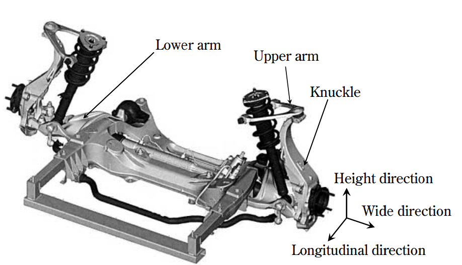
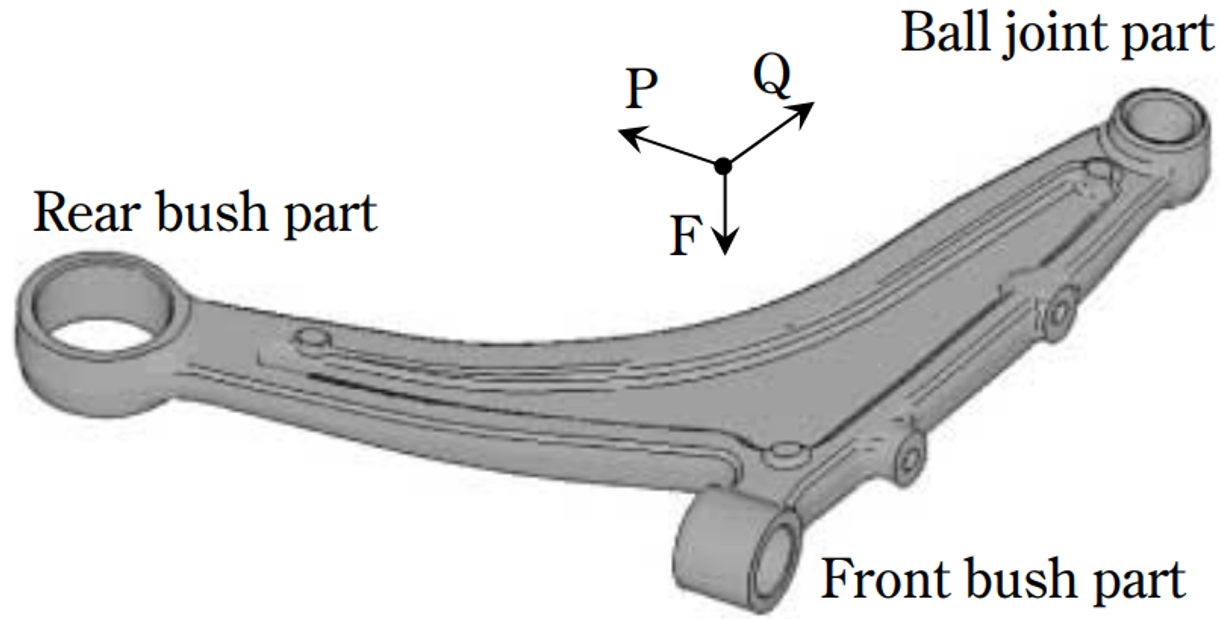
自動車向けロアアーム(Lower Arm)を今回の設計対象とします。ロアアームはタイヤと車体、サスペンションを繋いでタイヤが路面から受けた衝撃を直接的に緩和するサスペンションの土台となる部品で衝撃、振動を吸収する他に車の走行中の段差やコーナーリング時などに発生する前後左右の荷重の移動を受け止め乗り心地を良くする為に重要な役割をしています[1][2]。一方でロアアームの耐荷重性能を高めるためには、既存形状の寸法調整による従来の設計手法ではサイズを大きく、重量を重くせざるを得ずばね下の空間圧迫、重量増加につながってしまいます。しかし近年自動車のEV化にともない本体重量が増加傾向にあるため、各部材を少しでも軽量化することが求められており、その流れに逆らった設計をすることは現実的ではありません。そのため、高性能かつ軽量でコンパクトな形状を設計する必要があり、そのためには既存形状にとらわれない新たな設計手法を確立する必要があります。
設計条件
本記事では、以下の条件のもとで設計していきます。(条件の設定においては、公知文献[2]を参考にしています。)
・材料:アルミニウム合金
・製造方法:鋳造(両側引抜き)
・境界条件:以下の通り
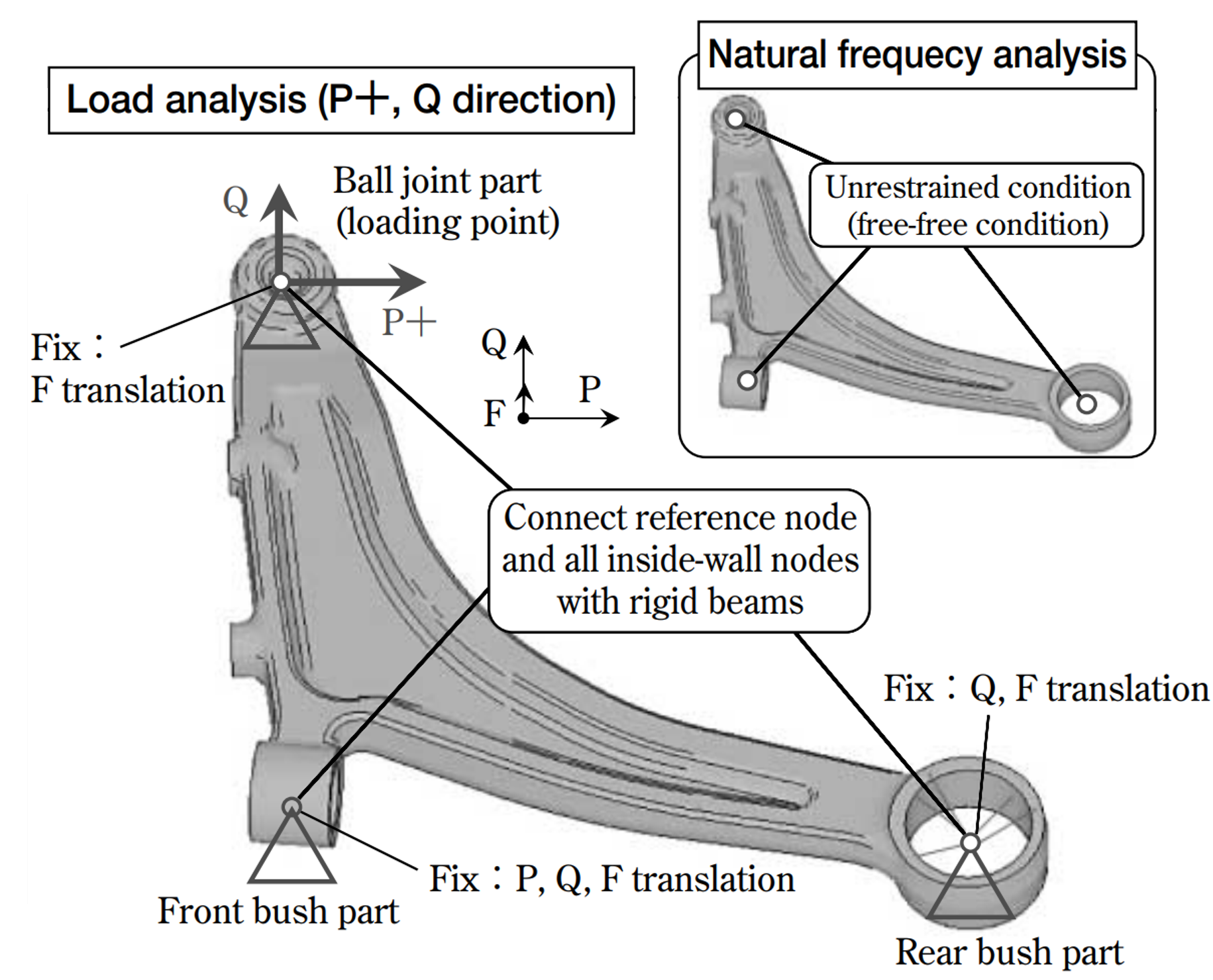
・設計領域(部材が占めることが許される領域):以下の通り
・制約条件(性能目標値):
・P方向荷重に対する剛性12.5kN/mm以上
・Q方向荷重に対する剛性168kN/mm以上
・P方向の降伏荷重24.6kN以上(⇒1kNのP方向荷重に対する相当応力10.1MPa以下)
・1次固有振動数547Hz以上
・目的関数:重量最小化(上記制約を満足する形状の中でできるだけ軽量な構造を設計する)
設計フロー
設計フローを大きく分けると以下の3つの段階になります。
1.トポロジー最適化による形状コンセプト探索
2.形状コンセプトのパラメトリックモデルへの落とし込み
3.パラメトリックモデルにおけるパラメータ最適化
それぞれの段階について、順を追って解説します。
設計フロー - 1.トポロジー最適化による形状コンセプト探索
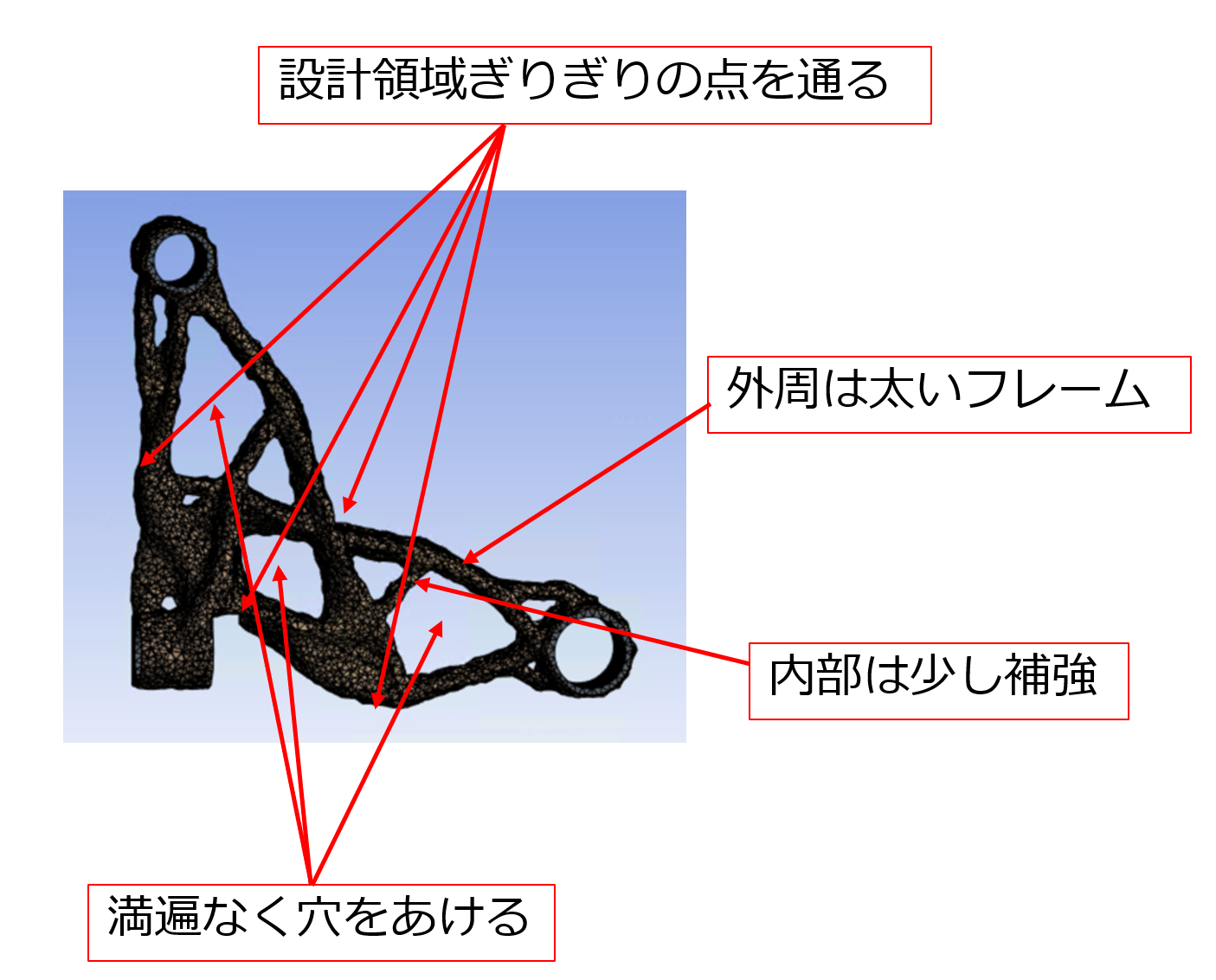
トポロジー最適化により形状設計の大まかな指針を決定します。トポロジー最適化については過去の記事( https://nature-architects.com/blog/1714/ )等を参照ください。トポロジー最適化で得られた形状は複雑でありそのままでは製造に適さず、多峰性の強い最適化問題なので局所解に陥っている可能性も高いため、あくまで指針の決定のみを行うことに留意する必要があります。そのため、この段階ではすべての制約条件を厳密に満たしている必要はありません。今回は以下のように複数の条件で最適化を実施しました。複数条件において共通して得られている構造は偶然出てきたものではなく真に重要な構造であると考えられます。
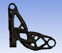
条件1 - 質量2.4kg(文献記載の従来形状と同等)のもとでP、Q方向荷重付加時の変位最小化。最適化アルゴリズムは密度法。
P方向剛性 = 14.1[kN/mm] (制約:≧12.48[kN/mm])
Q方向剛性 = 157.5[kN/mm] (制約:≧168[kN/mm])
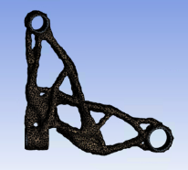
条件2 - 質量1.6kg(文献記載の従来形状の65%)のもとでP、Q方向荷重付加時の変位と応力最小化。最適化アルゴリズムは密度法。
P方向剛性 = 8.1[kN/mm] (制約:≧12.48[kN/mm])
Q方向剛性 = 203.9[kN/mm] (制約:≧168[kN/mm])
P方向1kN荷重付加時の相当応力最大値 = 12.7[MPa] (制約:≦10.1MPa)
条件3 - 質量1.6kg(文献記載の従来形状の65%)のもとでP、Q方向荷重付加時の変位と応力最小化。最適化アルゴリズムはレベルセット法。
P方向剛性 = 7.6[kN/mm] (制約:≧12.48[kN/mm])
Q方向剛性 = 37.1[kN/mm] (制約:≧168[kN/mm])
P方向1kN荷重付加時の相当応力最大値 = 10.6[MPa] (制約:≦10.1MPa)
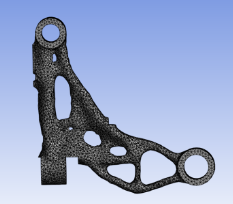
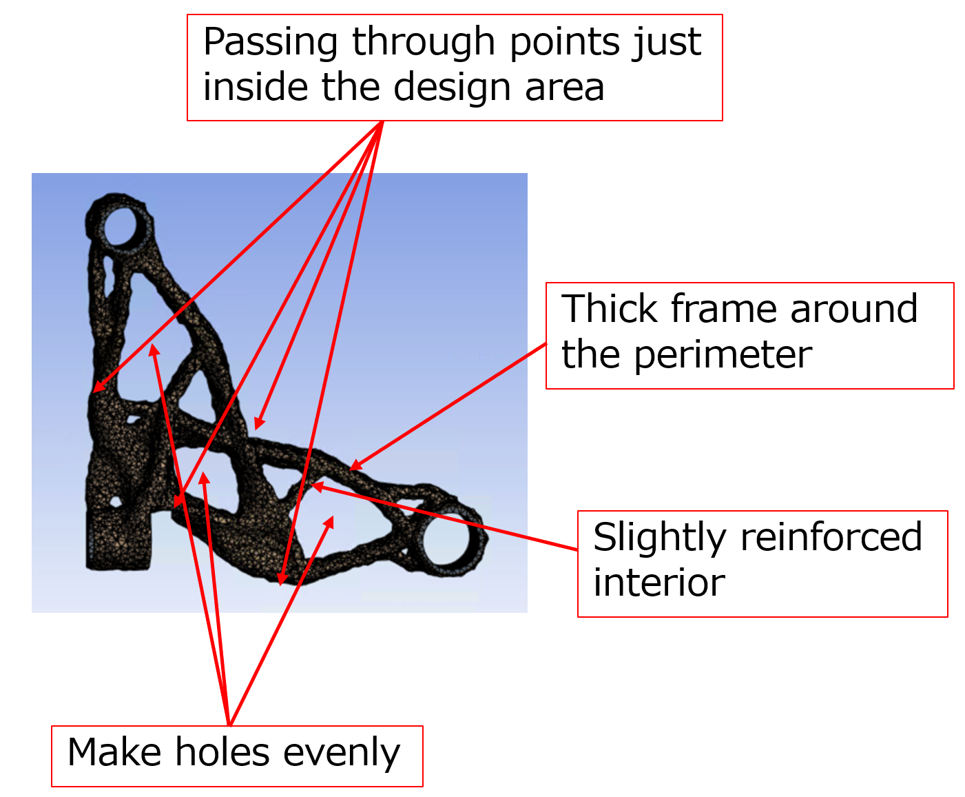
以上の形状から、以下の構造が重要であると考えました。
設計フロー - 2.形状コンセプトのパラメトリックモデルへの落とし込み
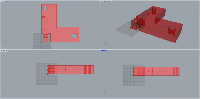
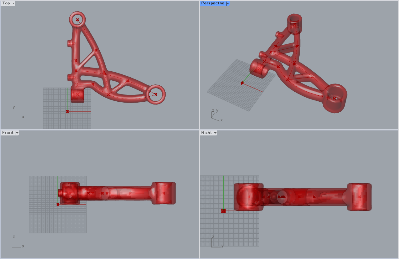
前ステップで得られた形状を、重要構造を押さえながらも、製造性を考慮したシンプルな形状でかつ最適化に適した少数のパラメータで表現できるモデルに落とし込みます。今回は20個のパラメータ(はりの太さや高さ、はりの通る座標など)で表現できる以下のようなモデルを作成しました。はりの太さを十分太く、またF方向(下図ではZ方向)について対称な形状にすることでF方向両側からの金型引抜きで製造できるようにしました。
設計フロー - 3.パラメトリックモデルにおけるパラメータ最適化
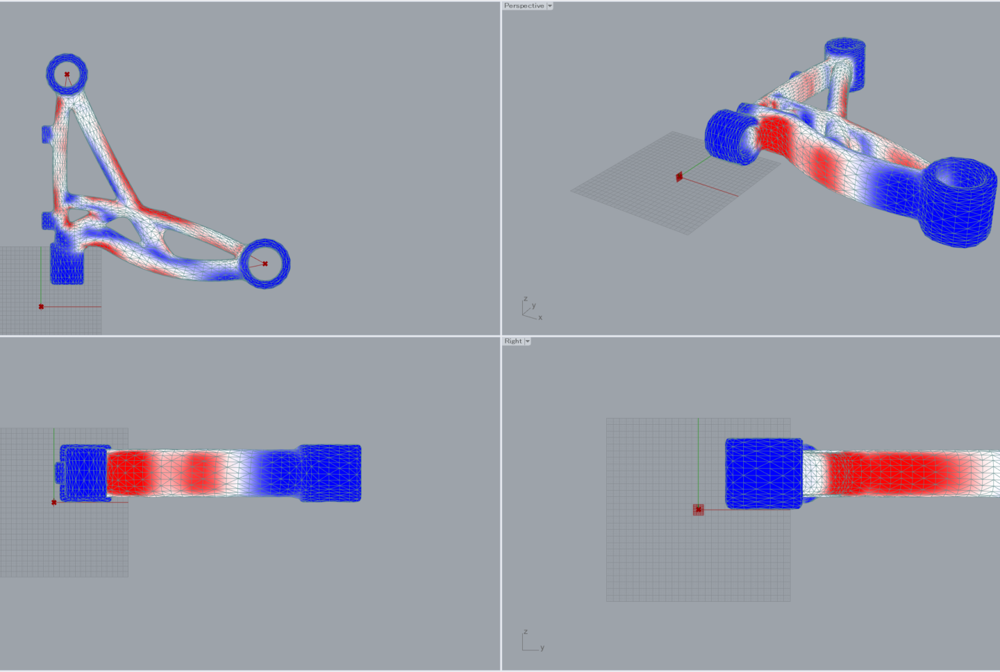
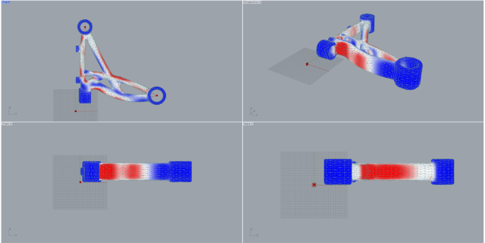
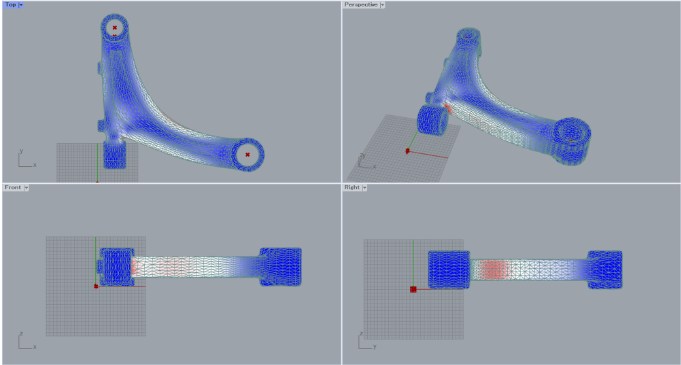
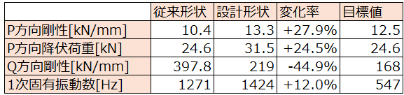
弊社ではCADソフトであるRhinoceros+grasshopper上でCAEソフトによるシミュレーションを実施し、パラメータを修正しながら何度もシミュレーションを繰り返す環境を独自に構築しており、それを利用してパラメータ最適化を行いました。1000回程度のシミュレーションで収束し、形状、性能は以下になりました。参考として、一般的な従来形状で同等の重量を持つロアアームの形状、性能も併記しています。設計形状では、従来形状では過剰性能であったQ方向剛性が下がる代わりに他の性能指標が大幅に上昇しています。また、カラーコンターはP方向荷重付加時の応力の相対的な分布(赤が大きい)を示しており、設計形状では従来形状に比べて部材全体に満遍なく応力がかかっており各部位を効果的に使えているのがわかります。
設計形状(最適化後最終形状)
従来形状
性能比較
まとめ
本記事では社内設計環境を用いた設計フローの一例について自動車向けロアアームの設計を題材として解説しました。紹介した内容からもわかるように、構造の最適化はCAEソフトが全て自動で実行するわけではなく、人の手で上手くハンドリングしなければならない場面が多いです。多くのものづくり企業では基礎研究レベルであり設計フローにはまだまだ組み込まれていない最適設計技術を弊社では実際に設計業務に適用して運用しているため、多くの知見やノウハウを有しており、最適設計を行う際の強みであると言えます。また、パラメトリックモデルにおけるパラメータ最適化の際にも、一般的には「CADソフトで形状生成⇒手動でCAEソフトにインポート⇒手動で複雑な境界条件を設定して解析実施⇒設計者が勘でパラメータ修正」という工程を何千回も繰り返すという大変な過程を経なければならないのに対し、全てをCADソフト上で自動で高速に行うことのできるソフトウェア環境を独自に構築していることについてもまた強みと言えるでしょう。
参考文献
[1]http://blog.kobac.co.jp/syaken/s-mamechishiki/8949
[2]https://www.kobelco.co.jp/technology-review/pdf/60_2/084-089.pdf
Design subject
The lower arm for automobiles is the subject of this design. The lower arm connects the tire, body, and suspension, and is the foundation of the suspension system that directly mitigates the impact of the tire from the road surface. It also plays an important role in improving ride comfort by absorbing front/rear and left/right load shifts that occur when driving over bumps or cornering [1][2]. On the other hand, in order to increase the load-bearing capacity of the lower arm, the conventional design method of adjusting the dimensions of the existing shape requires a larger size and heavier weight, which leads to increased space compression under the spring and increased weight. However, with the recent trend toward EVs, the weight of the vehicle body is increasing, and there is a need to reduce the weight of each component as much as possible. Therefore, it is necessary to design a high-performance, lightweight, and compact shape, and to do so, it is necessary to establish a new design method that is not bound by existing shapes.
Design Conditions
This article will be designed under the following conditions. (In setting the conditions, we refer to the public literature [2].)
Material: Aluminum alloy
Manufacturing method: Casting (double-sided pultrusion)
Boundary conditions: As follows
Design area (area allowed to be occupied by the member): As follows
Constraints (performance targets):
Stiffness against load in P direction: 12.5 kN/mm min.
Stiffness against load in Q direction: 168 kN/mm min.
Yield load in P direction: 24.6 kN or more (⇒Equivalent stress for 1 kN load in P direction: 10.1 MPa or less)
First-order natural frequency: 547 Hz or higher
Objective function: Weight minimization (design a structure that is as light as possible within a shape that satisfies the above constraints)
Design Flow
The design flow can be broadly divided into the following three stages
Shape concept exploration through topology optimization
- Shape concept incorporation into parametric model
Parameter optimization in the parametric model
Each of these stages is explained in turn.
Design flow - 1. Shape concept search by topology optimization
Topology optimization is used to determine a rough guideline for shape design. For more information on topology optimization, please refer to our previous article (https://nature-architects.com/blog/1714/). The shape obtained by topology optimization is complex and not suitable for manufacturing as it is, and since it is a highly multimodal optimization problem, it is highly likely to be stuck in a local solution. Therefore, it is not necessary to strictly satisfy all the constraints at this stage. In this case, optimization was performed under multiple conditions as follows. The structures commonly obtained in multiple conditions are considered to be truly important structures, and not those that emerged by chance.
Condition 1 - Minimization of displacement when load is applied in the P and Q directions under a mass of 2.4 kg (equivalent to the conventional geometry described in the literature). Optimization algorithm is density method.
P-directional stiffness = 14.1[kN/mm] (constraint: ≥12.48[kN/mm])
Q-direction stiffness = 157.5[kN/mm] (Constraint: ≧168[kN/mm])
Condition 2 - Displacement and stress minimization during P and Q direction load application under a mass of 1.6 kg (65% of the conventional geometry described in the literature). Optimization algorithm is density method.
P-directional stiffness = 8.1[kN/mm] (constraint: ≥12.48[kN/mm])
Q-direction stiffness = 203.9[kN/mm] (Constraint: ≧168[kN/mm])
Maximum equivalent stress at 1 kN load applied in P direction = 12.7[MPa] (Constraint: ≤ 10.1 MPa)
Condition 3 - Displacement and stress minimization under applied load in P and Q directions with a mass of 1.6 kg (65% of the conventional geometry described in the literature). Optimization algorithm is level set method.
P-directional stiffness = 7.6[kN/mm] (constraint: ≥12.48[kN/mm])
Q-direction stiffness = 37.1[kN/mm] (Constraint: ≧168[kN/mm])
Maximum equivalent stress at 1 kN load applied in P direction = 10.6[MPa] (Constraint: ≤ 10.1 MPa)
Based on the above geometry, we considered the following structure to be important.
Design Flow - 2. Shape Concepts into Parametric Models
The geometry obtained in the previous step is incorporated into a model that can be expressed with a small number of parameters suitable for optimization, while keeping the important structures in mind and keeping the geometry simple enough for manufacturability. In this case, we created the following model that can be expressed with 20 parameters (thickness and height of the beams, coordinates of the beams' paths, etc.). The beams are sufficiently thick and symmetrical in the F-direction (Z-direction in the figure below) so that they can be manufactured by pulling the die from both sides in the F-direction.
Parameter optimization in parametric model
We have built an environment in which simulations are repeated many times while modifying parameters, and we used this environment to perform parameter optimization. The simulation converged after about 1,000 simulations, and the shape and performance are shown below. For reference, the geometry and performance of a lower arm with the same weight and conventional geometry are also shown. In the designed shape, the Q-directional rigidity, which was excessive in the conventional shape, has been lowered, while other performance indices have increased significantly. The color contour shows the relative distribution of stress (red is larger) when a load is applied in the P direction.
Designed shape (final shape after optimization)
Conventional shape
Performance comparison

Summary
In this article, an example of a design flow using an in-house design environment was explained using the design of a lower arm for an automobile as the subject matter. As can be seen from the introduction, not all structural optimization is performed automatically by CAE software, and there are many situations where it must be handled successfully by human hands. Since our company actually applies and operates the optimal design technology, which is still at the basic research level and not yet incorporated into the design flow in many manufacturing companies, we have a great deal of knowledge and know-how, which is our strength when performing optimal design. In addition, parameter optimization in parametric modeling generally requires a very difficult process of "generating geometry in CAD software → manually importing into CAE software → manually setting complex boundary conditions and conducting analysis → designer's intuition to modify parameters," which is repeated thousands of times. In contrast, we have developed our own software environment that allows us to do everything automatically and at high speed on CAD software, which can also be considered a strength.
References.
[1]http://blog.kobac.co.jp/syaken/s-mamechishiki/8949
[2]https://www.kobelco.co.jp/technology-review/pdf/60_2/084-089.pdf
