
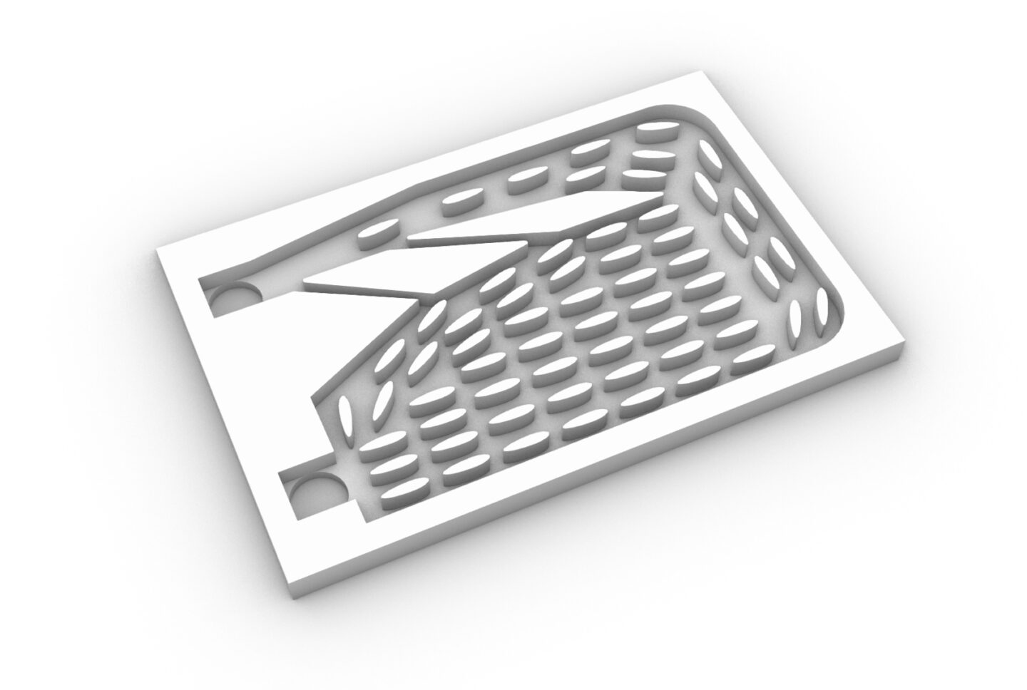
位相最適化(トポロジー最適化)とは
位相最適化(トポロジー最適化、Topology optimization)は所定の解析条件・制約で設計空間において材料配置を最適化する数学的手法です。
本記事で位相最適化の詳細な説明は省きますので、以下の資料など多くの説明資料がWeb上にありますのでそちらを参照ください。
https://www.jstage.jst.go.jp/article/jjspe/85/11/85_965/_pdf
また、弊社イベントOpenNAにおける米倉一男先生と矢地謙太郎先生のご講演でも位相最適化の基礎から応用まで説明がなされております。YouTubeに公開していますので、こちらもぜひご覧ください。
ヒートシンクの設計
位相最適化は問題設定をすればゼロから形状を生成する万能な手法に思えますが、実際は解くのが難しいセットアップもあれば、最適化を解くと適切でない結果が得られることあります。
本記事では、ヒートシンク設計事例についてを、設計の思想および、流体位相最適化を用いた設計で直面する課題の一例とその対処手段とともに説明します。
位相最適化にはCOMSOL Multiphysics®を使用し、矢地謙太郎先生の配布されている位相最適化のフレームワークを活用させていただきました。
問題設定
下図のように熱源の上に冷却プレートを置き、冷却プレート内部に液体を流して冷却する系を考えます。
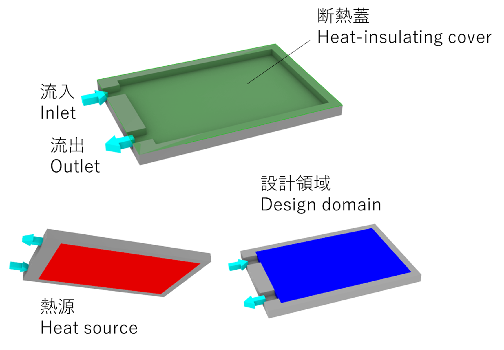
位相最適化のセットアップは以下のようにしました。細かい数値については省きます。
- 位相最適化モデル
- 冷却プレートを固体層と流体層の2層にモデル化(参考論文:doi.org/10.1016/j.ijheatmasstransfer.2019.118462)
- 密度法を使用
- 境界条件
- 流入口、流出口:圧力境界
- 熱源:一定エネルギーソース
- 壁面:断熱
- 目的関数
- 固体層の最大温度最小化
- 制約条件:なし
設計の思想
人の知見と位相最適化を組み合わせて、人だけでは思いつかない構造をつくるという思想で設計をしました。
位相最適化のみでは、設計上の様々な制約を考慮するのが難しかったり、設計対象全体を最適化すると現実的な時間では解けなかったたりして、適用できる設計問題が限られてしまいます。
また、人の知見のみで設計をすると、人が思いつく範囲でしか形状を考えることができず、設計可能な形状の範囲が狭くなってしまいます。
位相最適化と人のそれぞれの得意な部分を合わせることで、よりよい設計ができると考えています。
課題1:乱流性
課題の一つに流れの乱流の効果があります。
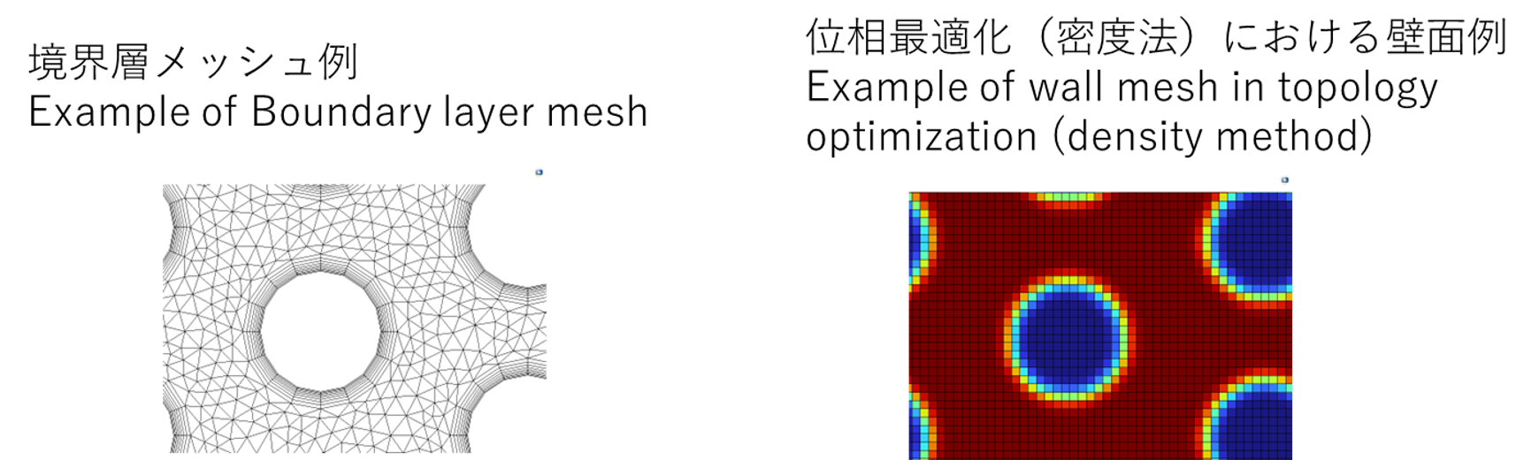
乱流状態の解析には一般に境界層を設けたうえで乱流モデルを使用しますが、壁面が最適化の過程で変化する位相最適化では設計領域全体を境界層相当のサイズのメッシュにする必要があります。
また、乱流の程度が強い場合には非定常解析が必要になることがあります。
研究において乱流モデルを用いた位相最適化や非定常状態の位相最適化は行われておりますが、設計への適用にはまだまだハードルが高いです。
今回の設計では、位相最適化をマルチフィデリティ解析のローフィデリティモデルの位置づけとして、物性値などを補正して層流・クリープ流れに近い状態で位相最適化を行っています。
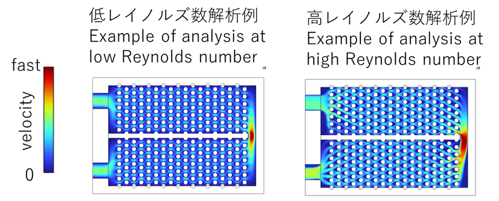
下図のように流れのレイノルズ数が変わると局所的な流れが変わりますが、大域的な流れは大きくは変わりません。位相最適化により層流状態で大域的な流れを探索し、大域的な流れを乱流状態でも再現できるよう形状を修正しつつ設計を行いました。
課題2:局所最適解
位相最適化は多自由度の最適化であるため、局所最適解が非常に多く存在しえます。
局所最適解が設計上意味のある結果であればいいのですが、問題設定によっては意味のない結果が出ることもあります。
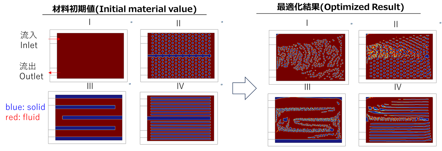
例えば今回のセットアップでは、以下の図のように各初期値に対して異なる最適化結果が得られます
今回の設計では、位相最適化の最適化結果を初期値にフィードバックして反復的に位相最適化を実行することで、設計において意味のある解に形状を誘導した設計を行いました。
位相最適化自体は勾配ベースな連続的な設計空間に対応しますが、最適化結果の初期値へのフィードバックは不連続な変化となります。
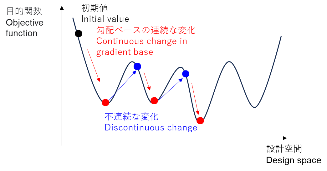
この不連続な変化を、最適化結果の物理・最適化の観点で人の解釈や探索・最適化アルゴリズム、社内の設計ノウハウをにより決めながら設計をしました。
課題3:製造性・可読性
位相最適化ではすべての製造上の制約を入れられないことが多く、最適化で得られた形状をそのまま使うことは難しいです。
そのため形状を修正することが必須ですが、形状の修正が性能にどのような影響を与えるかが単純には分かりません。
また仮に位相最適化で得られた形状をそのまま製造できたとしても、形状が複雑で品質管理が難しかったり、形状の意図がわからず設計変更が難しかったりして、妥当な設計といえない可能性が高いです。
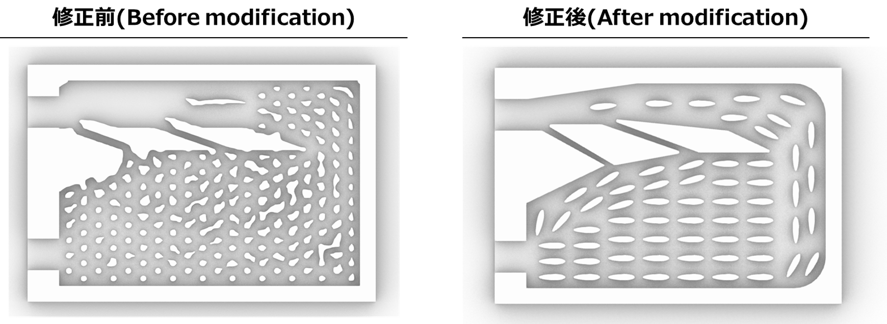
今回の設計では、位相最適化により得られた形状の物理的な意図を解釈したうえで、形状のコンセプトを抽出し形状を修正することで製造性・可読性を高めました。
例えば以下のようなコンセプトを抽出して、下図のように形状を修正しました。
- 冷却しやすい上流で流体の熱移動を少なくするため、上流空間は狭くし流体の滞在時間を短くする
- 冷却しにくい下流で流体の熱移動を大きくするため、下流空間は狭くし流体の滞在時間を長くする
- バイパス形状により冷たい流体を下流側へ短い経路で送る
設計結果
ここまで記載したように位相最適化で問題となることがある各課題を解決しながらヒートシンクを設計しました。
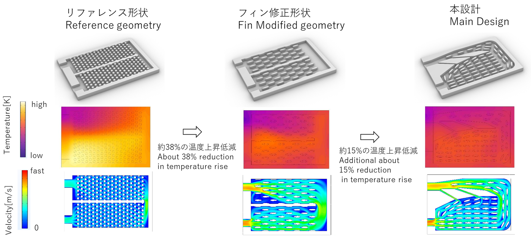
本設計の形状による冷却で、リファレンス形状比で温度上昇量を約47%、リファレンスのフィンを適切な密度に修正したもの比で15%低減しました。
まとめ
本記事では、位相最適化と人の手を組み合わせた、ヒートシンクの設計事例を紹介しました。
解析・最適化技術の発展に伴い、製品設計の行い方も変わりつつあります。
解析・最適化技術を設計にただ使うだけでなく、解析・最適化技術では手の届かない部分を人が補い適切にフィードバック・修正をかけていくことでより良い設計ができると考えています。
What is Topology Optimization ?
Topology optimization is a mathematical method to optimize the arrangement of materials in the design space under given analytical conditions and constraints.
We will not go into a detailed explanation of topology optimization in this article; please refer to the many explanatory materials available on the Web.
Please also check out the lectures by Dr. Kazuo Yonekura and Dr. Kentaro Yaji at our OpenNA event, where they explain the basics and applications of topology optimization.
Heat Sink Design
Topology optimization seems to be a universal method for generating geometry from scratch once the problem is set up, but in reality, some setups are difficult to solve, and solving the optimization may yield inappropriate results.
This article describes a heat sink design case study, along with design philosophy and examples of challenges faced in designing with thermo-fluid topology optimization and how to deal with them.
We used COMSOL Multiphysics® for topology optimization and took advantage of the topology optimization framework distributed by Dr. Kentaro Yaji.
Problem-Solving
As shown in the figure below, consider a system in which a cooling plate is placed above the heat source and liquid flows inside the cooling plate to cool it.
The topology optimization setup was as follows The detailed values are omitted.
- Topology optimization model
- Cooling plate modeled in two layers: solid layer and fluid layer(reference paper:doi.org/10.1016/j.ijheatmasstransfer.2019.118462)
- Use density method
- Boundary conditions
- Inlet, Outlet:Pressure fixed boundary
- Heat source:Constant energy sources
- Wall:Insulation
- Objective function
- Maximum temperature minimization of solid layer
- Constraints: None
Design Philosophy
The design was based on the idea of combining human knowledge with topology optimization to create a structure that could not have been conceived by humans alone.
Topology optimization alone is limited in its applicability to design problems because it is difficult to take into account various design constraints, and optimization of the entire design object cannot be solved in a realistic amount of time.
In addition, when design is based solely on human knowledge, the range of shapes that can be designed is limited because people can only think of shapes within the limits of what they can come up with.
We believe that topology optimization and people's respective strengths can be combined to create a better design.
Issue 1: Turbulence
One of the challenges is the effect of flow turbulence.
In general, a turbulence model is used with a boundary layer for analysis of turbulent conditions, but for topology optimization, where the wall surface changes during the optimization process, the entire design domain must be meshed with a size equivalent to that of the boundary layer.
Unsteady analysis may also be necessary when the degree of turbulence is strong.
Although topology optimization using turbulence models and unsteady state topology optimization has been done in research, there are still hurdles to overcome in its application to design.
In this design, topology optimization is positioned as a low-fidelity model in a multi-fidelity analysis, and topology optimization is performed in a state close to laminar and creep flow by correcting for physical properties and other factors.
As shown in the figure below, a change in the Reynolds number of the flow changes the local flow, but does not significantly change the global flow. The topology optimization was used to search for the global flow in laminar flow conditions, and the geometry was modified to reproduce the global flow in turbulent flow conditions.
Issue 2: Locally optimal solution
Because topology optimization is a multi-degree-of-freedom optimization, there can be a very large number of locally optimal solutions.
It would be nice if the locally optimal solution is a meaningful result for the design, but depending on the problem setting, it may not be meaningful.
For example, in this setup, different optimization results are obtained for each initial value, as shown in the following figure
In this design, the shape was guided to a meaningful solution in the design by running the topology optimization iteratively with the optimization results feedback to the initial values.
The topology optimization itself corresponds to a continuous, gradient-based design space, but the feedback of the optimization results to the initial values is a discontinuous change.
This discontinuous change was designed by human interpretation, search and optimization algorithms, and in-house design know-how in terms of the physics and optimization of the optimization results.
Issue 3: Manufacturability and readability
Topology optimization often cannot include all manufacturing constraints, so it is difficult to use the geometry obtained from optimization as is.
Therefore, it is essential to modify the geometry, but it is simply not clear how modifying the geometry will affect performance.
Even if the geometry obtained by topology optimization could be manufactured as is, it is highly likely that it would not be a valid design because the geometry is complex and quality control would be difficult, or design changes would be difficult because the intent of the geometry is unknown.
In this design, after interpreting the physical intent of the geometry obtained through topology optimization, the concept of the geometry was extracted and the geometry was modified to improve manufacturability and readability.
For example, we extracted the following concept and modified the shape as shown below.
- To reduce the heat transfer of fluid upstream where cooling is easier, the upstream space is narrower and the residence time of fluid is shorter.
- To increase fluid heat transfer downstream, where it is harder to cool, the downstream space is narrower and the fluid's residence time is longer.
- Bypass shape sends cold fluid downstream in a shorter path.
Design Results
Cooling with this design shape reduced the temperature rise by about 47% compared to the reference shape, and by 15% compared to the reference fins modified to the appropriate density.
Summary
In this article, we have presented a case study of a heat sink design that combines topology optimization and human hands.
With the development of analysis and optimization technologies, the way product design is conducted is changing.
We believe that better design can be achieved not only by using analysis and optimization technology in design, but also by having people supplement and provide appropriate feedback and correction to areas that cannot be reached by analysis and optimization technology.
