
はじめに
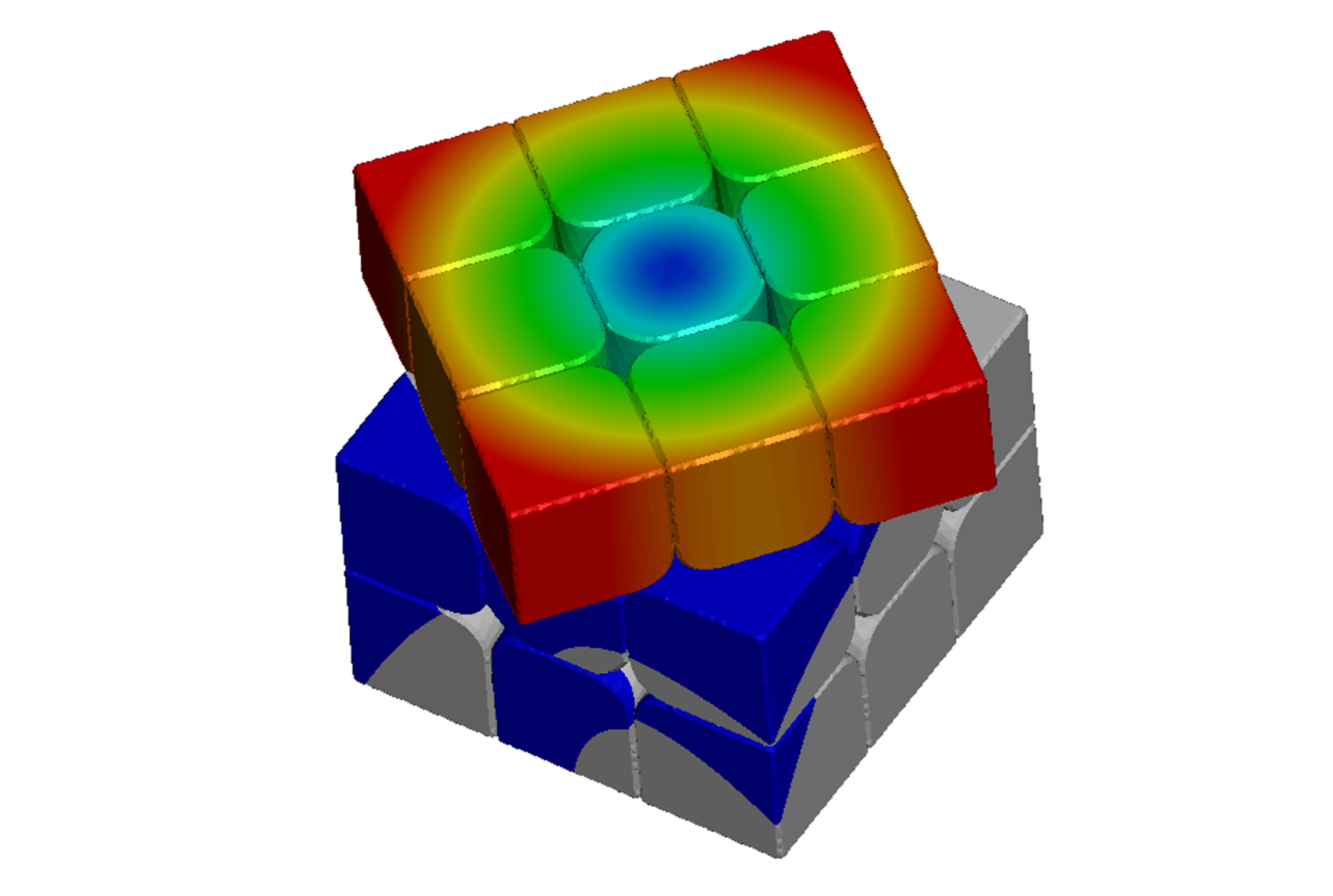
スピードキューブをご存知ですか?ルービックキューブ®に代表される立体パズルを速く解く競技のことです。最もポピュラーな3x3x3キューブ部門の現在の世界記録は3.13秒で、アメリカの選手が2023年に樹立しました[1][2]。
タイムの短縮には手順の短さと動かすスピードの両方が重要です。上記世界記録では完成までに要した手数は31手であり[3]、1秒間に約10手操作する計算となります。これほどの動きの実現には、指の鍛錬に加え、パズル自体のハードウェアとしての性能の進化も不可欠な要素となっています。
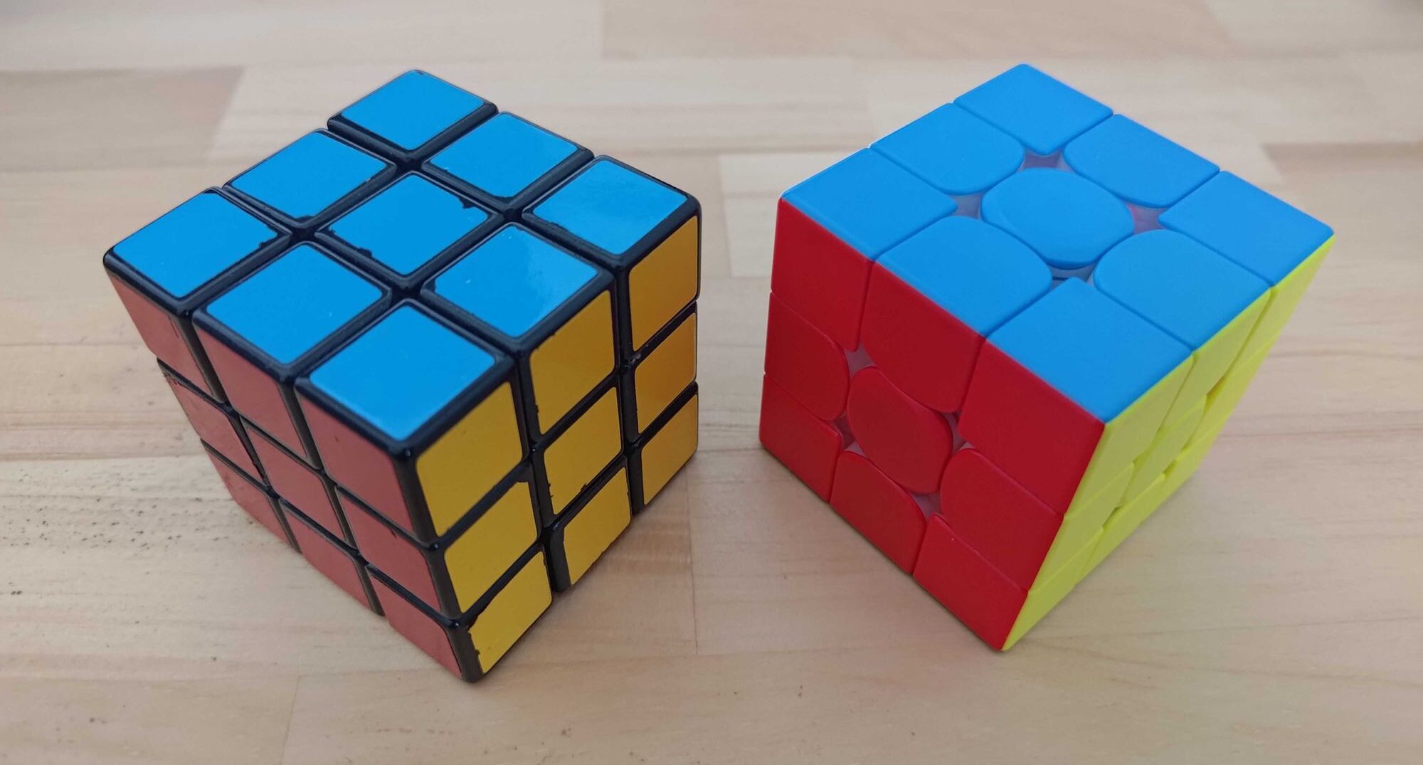
おもちゃメーカーが販売している一般的なキューブと、2010年以降に進化した競技用のもとを触り比べると、だれもが滑らかさの違いに驚くでしょう。どのような設計よってこの滑らかさを実現しているのでしょうか。
本記事では、動的陽解法を用いたシミュレーションを通じて、競技用パズルの回転の滑らかさがどう実現されているのか考察します。
解析対象動作
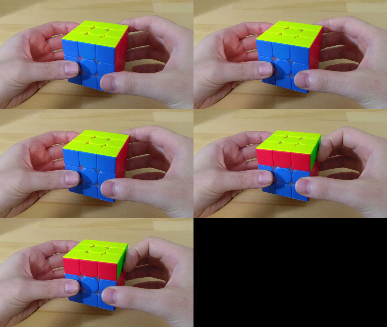
今回解析する現象は以下の動きです。人差し指で上側の面を90度回転させる「トリガー」と呼ばれるもので、キューブを解く際に頻出する最も基本的な動作と言えます。
動画をコマ送りにして計測したところ、トリガー1回に要する時間は0.03s~0.04sでした。
動的陽解法
シミュレーションには動的陽解法を用います。
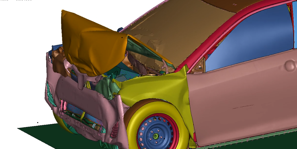
動的陽解法では運動方程式から求めた加速度を時間積分することで、次ステップの速度及び変位を順次計算します。陰解法と異なり、各時間ステップで連立方程式を解く必要がないため、1ステップあたりの計算コストが小さい一方、時間ステップは細かく取る必要があります。そのため衝突現象などの、非線形性が強く短時間の解析に適しています。
キューブの機構
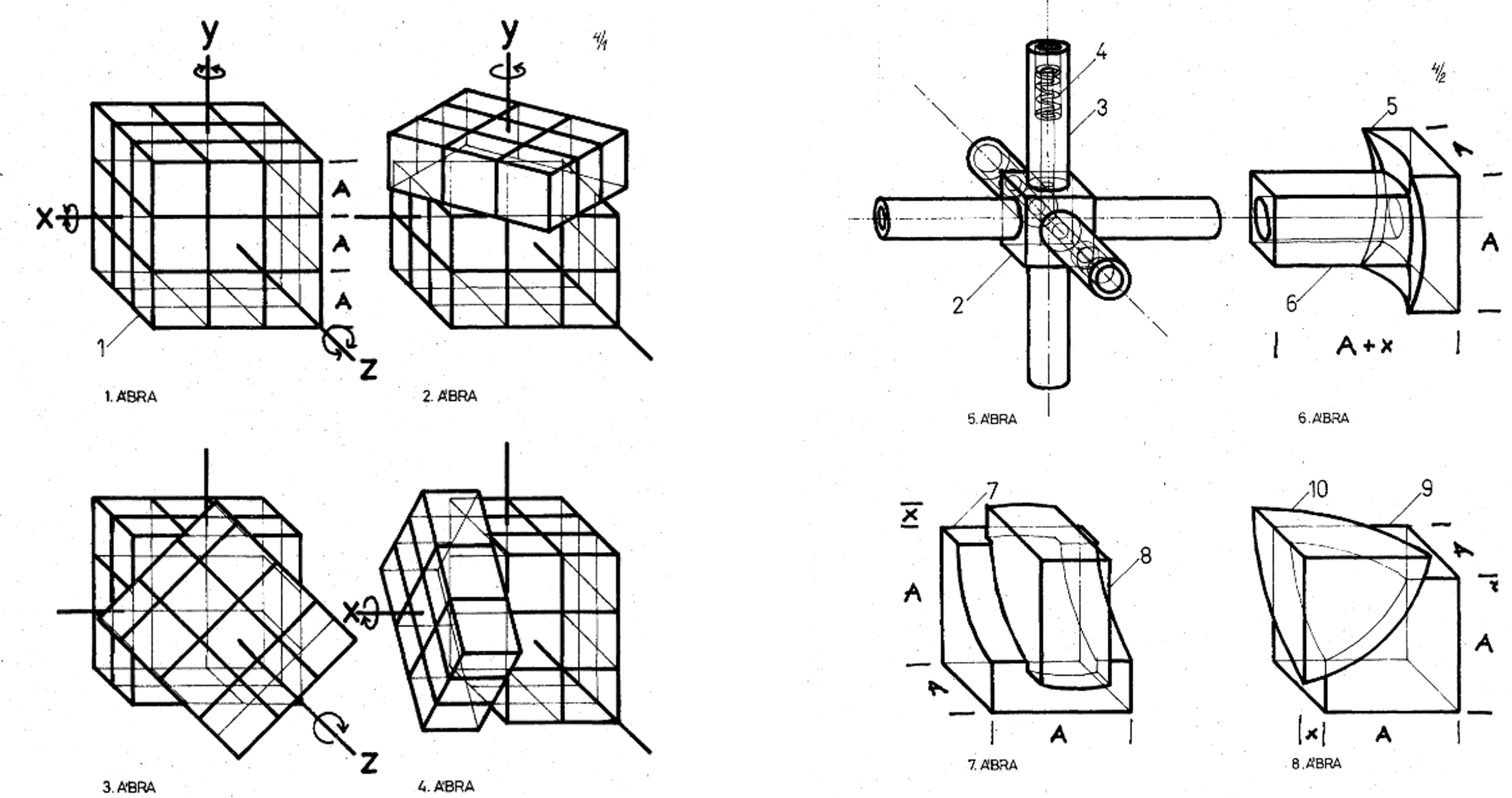
26個の立方体がばらばらになることなく6軸周りに自由に動かせる画期的な機構は、1974にハンガリーの建築学者であるルービック氏によって発明されました。
表面に見えるセンターキューブ、エッジキューブ、コーナーキューブと、内部のコアの計4種類の部品で構成されます。この基本的な構成は最新の競技用キューブでも変わっていません。
3Dモデルの作成
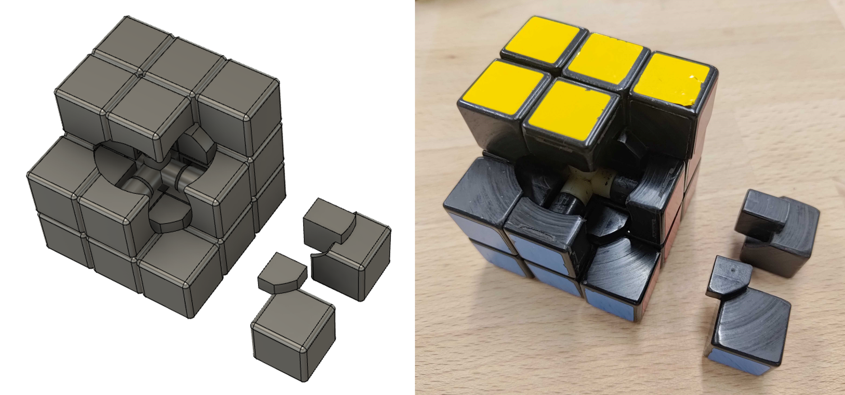
冒頭の写真にあった2つのキューブを解析対象とし、分解・計測し3Dモデルを作成しました。
こちらが2008年頃に購入した古典的な構造のキューブ。各部品の形状は特許図面とほぼ同じです。回転は重いですが、玩具安全基準STのマークが箱についていており、おもちゃとしてしっかりと作られている印象です。
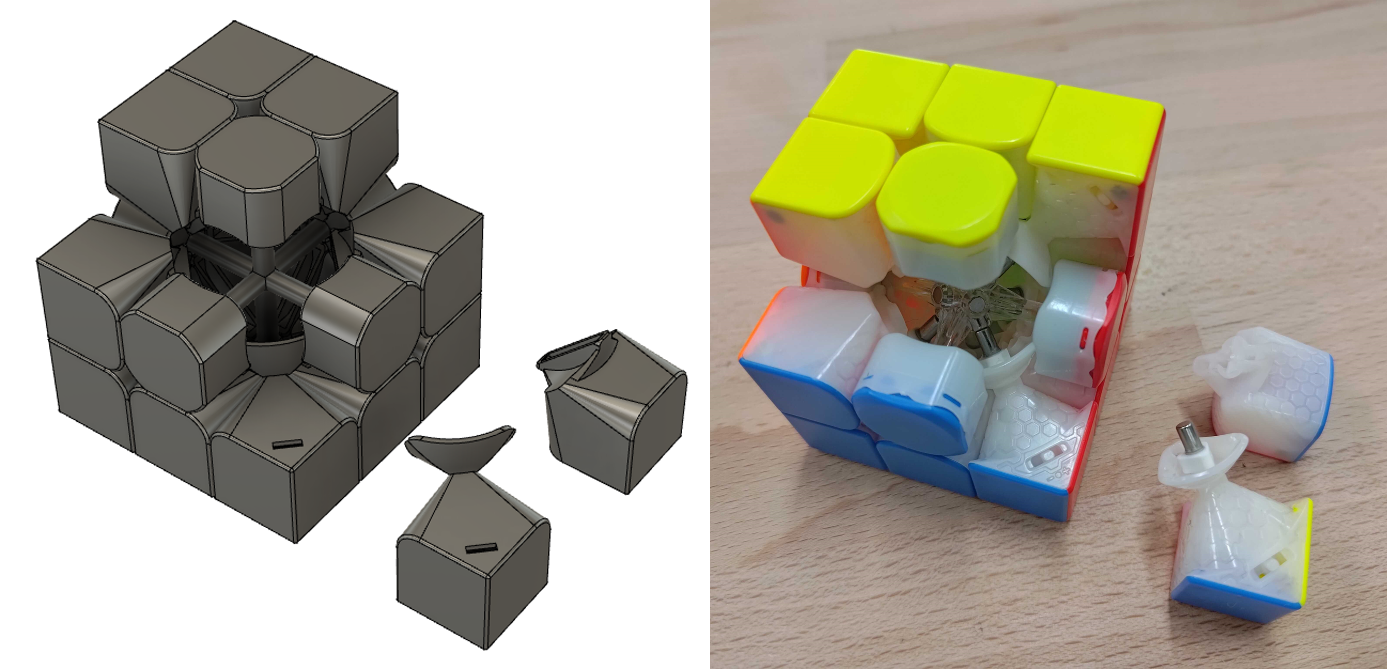
こちらが2022年に購入した競技用キューブのハイエンド機種。基本的な構成は同一ですが、角部のRが大きく取られている、中央の軸が細い、といった点が目につきます。また部品の肉厚も薄くしてあり、重量が軽いです。
実物には他にも、マグネットにより90度毎にピタッと止まる機能や、軸の締付具合の調整機構、潤滑油の馴染を良くするため(?)の表面のハニカム状の溝、といった多くの工夫が見られるのですが、本記事では純粋に形状と滑らかさの関係に着目したいため割愛します。
解析上のモデル化
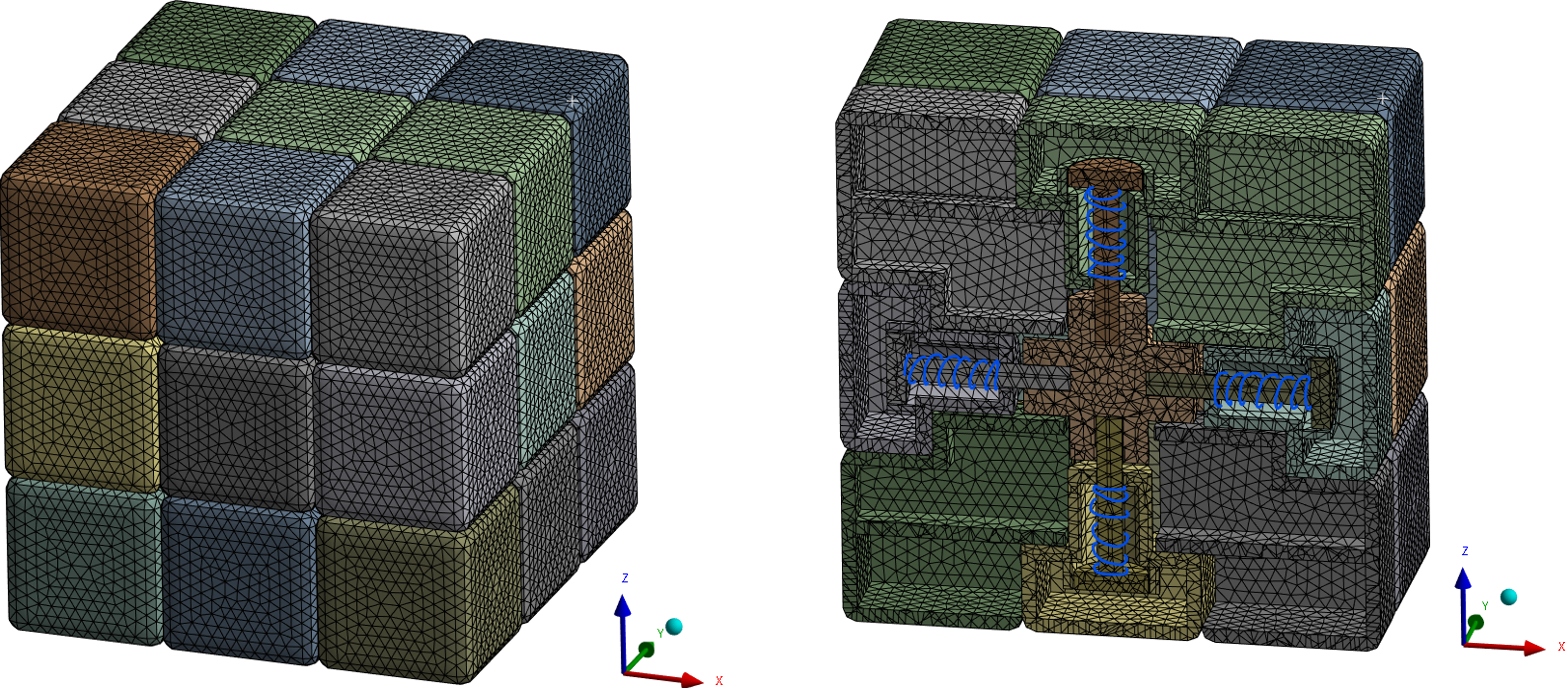
解析上のモデル化は以下の通りとしました。
- 材料モデル:剛体
- 物性値:ABS樹脂を想定(剛体のため弾性率は接触剛性の計算にのみ用いられる)
- 摩擦係数:静摩擦係数0.1/ 動摩擦係数0.05
- コアから伸びるピンとセンターキューブの接続:円筒ジョイント拘束+ 1次元バネ要素
バネには、寸法公差の吸収や、操作時の各ピースの位置が理想状態からずれた場合でもスムーズに回転させる役割があります。新キューブでは、この部分が磁石に置き換えられているのですが、条件を合わせるため本解析では同一のバネ要素としてモデル化しています。
評価項目1:回転の軽さ
まず回転させるときの抵抗を評価します。以下の境界条件でトリガーを模擬した強制変位を与え、要したエネルギーの内訳を分析します。固定箇所はトリガー動作の際の指の当たり方を模しています。強制変位は0.03s間で与えました。
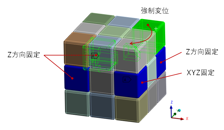
結果は以下となりました。
旧構造では90度回転に要する外部仕事が164mJであるのに対し、新構造では91.9mJまで減少しています。
内訳に注目すると運動エネルギの減少は、肉薄化による軽量化によるものです。
接触エネルギの減少には摩擦力が関係しています。以下でその理由を考察します。
| 古典的構造 | 新構造 | 改善率 | |
|---|---|---|---|
| 外部仕事 [mJ] | 164 | 91.9 | -44.0% |
| 運動エネルギ[mJ] | 21.7 | 12.8 | -41.0% |
| 接触エネルギ[mJ] | 146 | 79.0 | -45.9% |
キューブの回転部の機構は、上段の1層と中段1層とで滑り軸受を構成していると捉えることができます。
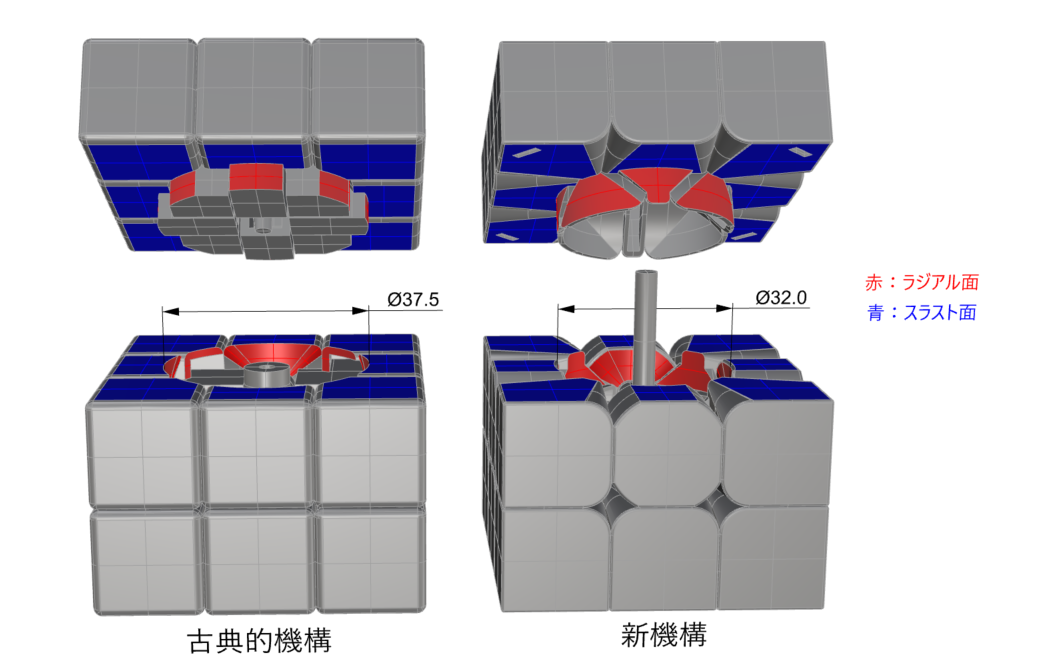
接触エネルギの内、上記滑り軸受部については、ラジアル面でで発生するエネルギと、スラスト面で発生するエネルギとに分解できます。両方とも低下していますがラジアル方向の方が低下幅が大きくなっています。
| 古典的構造 | 新構造 | 改善率 | |
|---|---|---|---|
| 接触エネルギ[mJ] | 146 | 79.0 | -45.9% |
| ラジアル成分[mJ] | 72.5 | 33.0 | -54.5% |
| スラスト成分[mJ] | 53.1 | 35.7 | -32.8% |
| その他[mJ] | 20.4 | 10.3 | -49.5% |
すべり軸受の摩擦によるトルクは以下の式で表せるので、摩擦する円筒面の直径が小さい新構造ではトルクが小さくなることがわかります。(\(L\) : 荷重、\(r\):軸受半径、\(\phi\):摩擦角)
\(M=Lr \sin \phi\)
スラスト方向は以下の式です。摩擦面が中心から離れた位置にあるほどモーメントへの寄与が大きくなるため、より内側においても接触している新構造のほうがトルクが小さくなることが推測されます。(\(\mu\):摩擦係数、\(P\):荷重、\(A\):接触面積)
\(M
=\frac{P}{A}\int_A \mu r dA\)
これらの式から見積もられる改善率は以下となり、数値解析で求めた値よりも改善率は低くなりました。
| 改善率 | |
|---|---|
| ラジアル成分 | -17.2% |
| スラスト成分 | -13.3% |
各摩擦力の計算式に登場する荷重は両キューブで等しいと仮定して計算していますが、解析では強制変位としていたため、新構造の方が荷重が小さく、より大きな差となったと考えられます。
とはいえ定性的には対応しており、摩擦箇所の寸法が回転の軽さに寄与していると言えそうです。
評価項目2:安定性
第2の項目としてキューブ操作時の安定性をみていきます。回転がいくら軽くても、思いきり速く回したときや、力を与える方向が若干変化したときに部品同士が引っかかると、大きなタイムロスに繋がります。
境界条件は以下のとおりです。強制変位ではなく、人差し指が当たる面に荷重を与えている点が先ほどとは異なります。
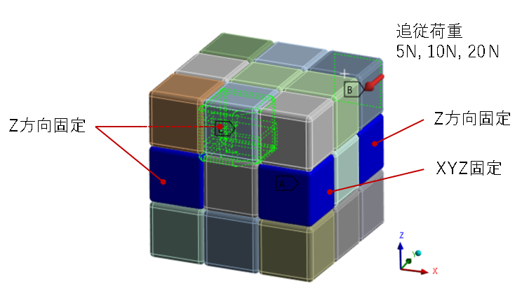
結果は以下となりました。古典的構造では10Nでは90度回っていますが、20Nでは90度回転する前に引っかかって止まっています。一方の新構造ではどの荷重に対してもスムーズに回転していることがわかります。
引っかかりの有無の原因について考察します。
古典的機構の20Nでは38度程度回転した時点で以下の図のように、手前側のコーナーキューブが-Z方向に変位し、その結果中段左側のエッジキューブの角に衝突しています。一方新機構20Nでは-Z方向の変位が低減されています。
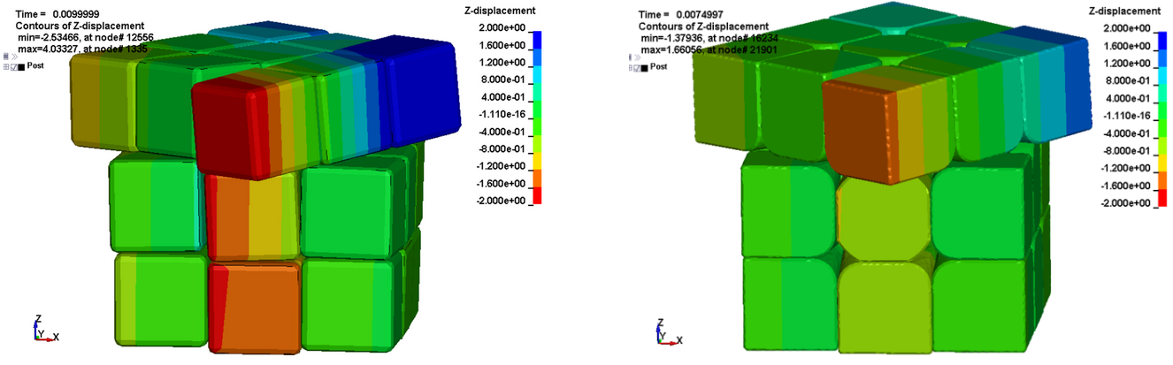
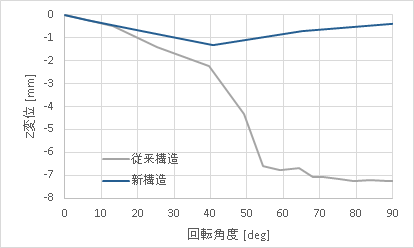
一見すると新機構では各パーツの角Rの大きさによって衝突後に進行方向が変化し、引っ掛かりを免れているように見えますが、以下のように衝突箇所の接点の変位を比較すると、実は衝突前にZ方向変位の差が開いていることがわかります。
Z変位軽減の理由は各部品のかみ合わせ部の形状にあります。45度回転させたときのコーナーキューブ(赤)の爪のかかりを、センターキューブを非表示にして比較します。
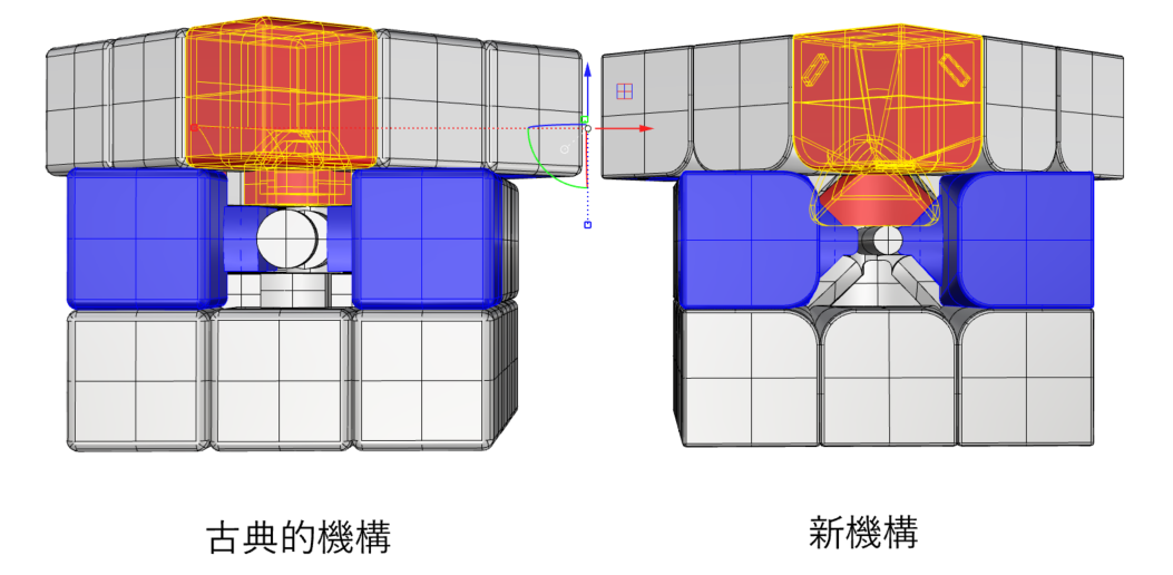
古典的機構ではコーナーキューブの爪は完全に見えており、非表示にしたセンターキューブのみにかかって保持されていることがわかります。
一方、新機構では両側のエッジキューブ(青)に同時にかかっており、センターキューブのみにかかる瞬間がありません。エッジキューブ(青)は親指を模した拘束に支えられているので、結果的に新機構ではコーナーキューブの-Z方向への変位が小さくなったと考えられます。
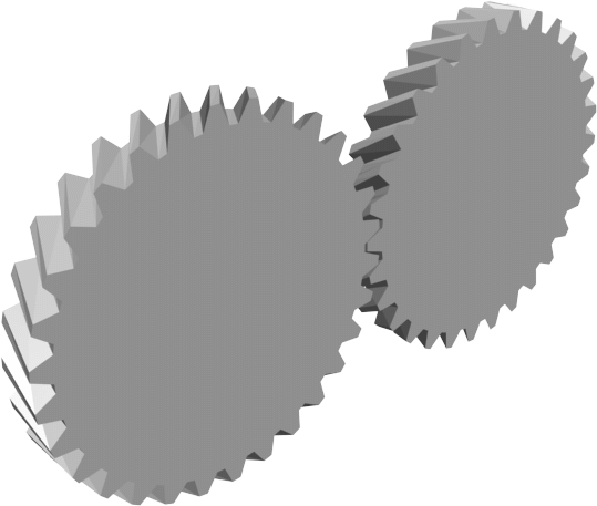
歯車に例えるなら、はすば歯車は平歯車よりも噛み合い率が高くなり、騒音が抑えられることと似ています。
最後に
本記事では動的陽解法を用いて競技用立体パズルの滑らかさの秘密に迫りました。かみ合い部の直径が回転の軽さに、同時に噛み合うパーツの数が安定性や滑らかさに寄与していることがわかりました。
競技用キューブがスムーズであることは触るとすぐに分かりますが、その理由についてあまり言及されておらず、どちらかというと目に付く磁石や調整機構が注目されることが多いと思います。今回解析してみることでどの形状がどのように寄与しているのかある程度知ることができました。
マニアックな内容にも関わらず最後までお読みいただきありがとうございました。
参考文献
[1] World Cube Association. "Rankings". WCA website. 2024/06/06. https://www.worldcubeassociation.org/results/rankings/333/single. (2024/06/06閲覧).
[2] @RubiksCube, "Max Park New Rubik’s Cube World Record 3.13 seconds". YouTube. 2023/06/12. https://www.youtube.com/watch?v=0DqfNLxaVi4. (2024/06/06閲覧).
[3] @TetraCubing, "Reconstruction of Max Park's 3.13 3x3 Rubik's Cube World Record Single!". Youtube. 2023/06/12. https://www.youtube.com/watch?v=PUZvVoagTbk. (2024/06/06閲覧).
[4] Center for Collision Safety and Analysis. "
2012 Toyota Camry Detailed Finite Element Model". CCSA website. 2016.06. https://www.ccsa.gmu.edu/models/2012-toyota-camry/. (2024/06/06閲覧).
[5] Rubik Ernő. "Térbeli logikai játék". ハンガリー特許170062. 1975/01/30. https://ruwix.com/the-rubiks-cube/rubiks-cube-patent-intellectual-property/. (2024/06/06閲覧).
Introduction
Have you heard of speedcubing? It is a sport that involves solving three-dimensional puzzles, like the Rubik's Cube®, as quickly as possible. The current world record for the most popular 3x3x3 cube category is 3.13 seconds, set by an American competitor in 2023 [1][2].
Both the brevity of the steps and the speed of movement are important for shortening the time. In the above world record, the number of moves required for completion was 31 [3], which means that approximately 10 moves were operated per second. To achieve such a level of movement, not only training the fingers but also the evolution of the puzzle's hardware performance is essential.
Comparing a typical cube sold by toy manufacturers and a competitive model that has evolved since 2010, anyone would be surprised by the difference in smoothness. How is this smoothness achieved through design?
In this article, we will consider how the smooth rotation of competitive puzzles is realized through simulations using the dynamic explicit method.
Analyzed Movement
The phenomenon analyzed this time is the following movement. It is called the "trigger," which rotates the upper face 90 degrees with the index finger, and it is the most basic movement frequently used when solving a cube.
When measured by frame-by-frame video analysis, the time required for one trigger was 0.03s to 0.04s.
Dynamic Explicit Method
We use the dynamic explicit method for the simulation.
In the dynamic explicit method, acceleration obtained from the equations of motion is integrated over time to sequentially calculate the next step's speed and displacement. Unlike the implicit method, there is no need to solve simultaneous equations at each time step, so the computational cost per step is low. However, the time step needs to be fine, making it suitable for short-term analyses with strong nonlinearity, such as collision phenomena.
Cube Mechanism
The groundbreaking mechanism that allows 26 small cubes to move freely around six axes without falling apart was invented in 1974 by Hungarian architect Ernő Rubik.
It consists of four types of parts: the visible center cubes, edge cubes, and corner cubes, and the internal core. This basic structure has not changed in the latest competitive cubes.
Creation of the 3D Model
The two cubes shown in the opening photo were disassembled, measured, and modeled in 3D for analysis.
Here is the cube with a classic structure purchased around 2008. The shape of each part is almost the same as the patent drawings. The rotation is heavy, but it has the toy safety standard ST mark on the box, giving the impression of being well-made as a toy.
Here is the high-end model of a competitive cube purchased in 2022. The basic structure is the same, but the corners have larger radii, the central axis is thin, and the parts are thinner and lighter.
In addition to these features, the actual model includes many other innovations, such as a mechanism that snaps into place every 90 degrees with magnets, an adjustment mechanism for the tightness of the axis, and honeycomb-shaped grooves on the surface to improve lubricant distribution. However, this article focuses purely on the relationship between shape and smoothness, so these aspects are omitted.
Modeling for Analysis
The modeling for analysis was as follows.
- Material Model: Rigid body
- Physical Properties: Assuming ABS resin (elastic modulus is used only for calculating contact stiffness due to rigidity)
- Friction Coefficient: Static friction coefficient 0.1/ Dynamic friction coefficient 0.05
- Connection between the pin extending from the core and the center cube: Cylindrical joint constraint + 1D spring element
The spring absorbs dimensional tolerances and allows smooth rotation even if the position of each piece deviates from the ideal state during operation. In the new cube, this part is replaced by a magnet, but for consistency, the same spring element is used in this analysis.
Evaluation Item 1: Ease of Rotation
First, we evaluate the resistance when rotating. A forced displacement simulating the trigger was applied under the following boundary conditions, and the breakdown of the required energy was analyzed. The fixed points simulate how the fingers hit during the trigger action. The forced displacement was applied over 0.03 seconds.
The results are as follows.
In the old structure, the external work required for a 90-degree rotation is 164mJ, while in the new structure, it has decreased to 91.9mJ.
Focusing on the breakdown, the reduction in kinetic energy is due to the weight reduction by thinning the parts.
The reduction in contact energy is related to the frictional force. The reason for this will be considered below.
| Classic Structure | New Structure | Improvement Rate | |
|---|---|---|---|
| External Work [mJ] | 164 | 91.9 | -44.0% |
| Kinetic Energy [mJ] | 21.7 | 12.8 | -41.0% |
| Contact Energy [mJ] | 146 | 79.0 | -45.9% |
The mechanism of the cube's rotating part can be seen as a sliding bearing composed of one upper layer and one middle layer.
Of the contact energy, the sliding bearing part can be divided into the energy generated on the radial surface and the energy generated on the thrust surface. Both have decreased, but the radial direction has a larger decrease.
| Classic Structure | New Structure | Improvement Rate | |
|---|---|---|---|
| Contact Energy [mJ] | 146 | 79.0 | -45.9% |
| Radial Component [mJ] | 72.5 | 33.0 | -54.5% |
| Thrust Component [mJ] | 53.1 | 35.7 | -32.8% |
| Other [mJ] | 20.4 | 10.3 | -49.5% |
The torque due to the friction of the sliding bearing can be expressed by the following equation, so the torque will be smaller in the new structure with a smaller diameter of the frictional cylindrical surface. (\(L\): Load, \(r\): Bearing radius, \(\phi\): Friction angle)
\(M=Lr \sin \phi\)
The thrust direction is as follows. The farther the friction surface is from the center, the greater the contribution to the moment, so the new structure, which also contacts closer to the center, is expected to have a smaller torque. (\(\mu\): Friction coefficient, \(P\): Load, \(A\): Contact area)
\(M=\frac{P}{A}\int_A \mu r dA\)
The estimated improvement rate from these equations is as follows, and the improvement rate is lower than the values obtained by numerical analysis.
| Improvement Rate | |
|---|---|
| Radial Component | -17.2% |
| Thrust Component | -13.3% |
The load appearing in each friction force calculation formula is assumed to be equal for both cubes, but since the analysis was based on forced displacement, it is thought that the load was smaller in the new structure, resulting in a larger difference.
Nonetheless, qualitatively it corresponds, and it seems that the dimensions of the friction points contribute to the ease of rotation.
Evaluation Item 2: Stability
The second item looks at the stability of the cube operation. No matter how light the rotation is, if the parts get stuck when turned very quickly or when the direction of force application changes slightly, it can lead to significant time loss.
The boundary conditions are as follows. Unlike the previous analysis, a load is applied to the surface where the index finger hits, rather than forced displacement.
The results are as follows. In the classic structure, the cube rotates 90 degrees with a 10N force, but stops before rotating 90 degrees with a 20N force. On the other hand, the new structure rotates smoothly with any load.
Consideration of the causes of getting stuck.
In the classic mechanism at 20N, the front corner cube displaces in the -Z direction at about 38 degrees of rotation, resulting in a collision with the corner of the middle left edge cube as shown in the figure below. In the new mechanism at 20N, the -Z direction displacement is reduced.
At first glance, it seems that the larger corner radius of the parts in the new mechanism allows it to avoid getting stuck by changing direction after the collision. However, comparing the displacement of the contact points before and after the collision, it becomes clear that the difference in Z-direction displacement opens up before the collision.
The reason for the reduced Z-displacement lies in the shape of the mating parts. The engagement of the corner cube (red) when rotated 45 degrees is compared with the center cube hidden.
In the classic mechanism, the claw of the corner cube is completely visible, and it is held only by the hidden center cube.
In contrast, in the new mechanism, it simultaneously engages with both edge cubes (blue), and there is no moment when it only engages with the center cube. The edge cubes (blue) are supported by constraints that simulate the thumb, so in the new mechanism, the corner cube's -Z direction displacement is considered to be smaller.
This is similar to how helical gears have a higher engagement rate than spur gears, reducing noise.
Conclusion
In this article, we delved into the secret of the smoothness of competitive three-dimensional puzzles using the dynamic explicit method. We found that the diameter of the engagement parts contributes to the ease of rotation, and the number of simultaneously engaging parts contributes to stability and smoothness.
While the smoothness of competitive cubes is immediately apparent upon touching them, the reasons for it are not often mentioned, with more attention paid to visible features such as magnets and adjustment mechanisms. Through this analysis, we were able to understand to some extent how each shape contributes.
Thank you for reading through to the end despite the niche content.
References
[1] World Cube Association. "Rankings". WCA website. 2024/06/06. https://www.worldcubeassociation.org/results/rankings/333/single. (Accessed: 2024/06/06).
[2] @RubiksCube, "Max Park New Rubik’s Cube World Record 3.13 seconds". YouTube. 2023/06/12. https://www.youtube.com/watch?v=0DqfNLxaVi4. (Accessed: 2024/06/06).
[3] @TetraCubing, "Reconstruction of Max Park's 3.13 3x3 Rubik's Cube World Record Single!". YouTube. 2023/06/12. https://www.youtube.com/watch?v=PUZvVoagTbk. (Accessed: 2024/06/06).
[4] Center for Collision Safety and Analysis. "2012 Toyota Camry Detailed Finite Element Model". CCSA website. 2016.06. https://www.ccsa.gmu.edu/models/2012-toyota-camry/. (Accessed: 2024/06/06).
[5] Rubik Ernő. "Térbeli logikai játék". Hungarian Patent 170062. 1975. https://ruwix.com/the-rubiks-cube/rubiks-cube-patent-intellectual-property/. (Accessed: 2024/06/06).

