
はじめに
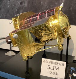
2024年1月、宇宙航空研究開発機構(JAXA)で開発された小型月着陸実証機 SLIM(Smart Lander for Investigating Moon)の月面着陸のニュースが報じられました。報告によると、主ミッションの100m精度ピンポイント着陸という目的を見事に達成しつつも、着陸後の停止姿勢が悪く太陽光パネルでの発電が難しい状態になってしまったようです[1][2]。
月面への着陸に対しては、衝撃吸収部材の開発とともに、実機でのドロップ試験、数値解析による検証が繰り返し行われます。
現在は各国の宇宙機関のみならず、民間企業までもが研究、営利化など様々な目的をもって月面を目指す時代になりました。月活用の第一ステップとして、月の土壌への安全な着陸は、多くの人にとって非常に興味深いテーマとなっていることでしょう[3]。
この記事では、着陸における衝突対象物である月面の土壌(Regolith)について、数値解析を行うために必要な材料モデルを作成し、着陸を模擬したドロップ試験の衝突解析への影響を考察してみます。
月の土壌(レゴリス)
まずは、月の土壌について一般的な知識を確認します。惑星科学においては、月、惑星・小惑星などの天体の表面に分布する堆積層をレゴリスと呼びます。以下、本記事では月表面の土壌を形成する粒子をレゴリスと呼びます。
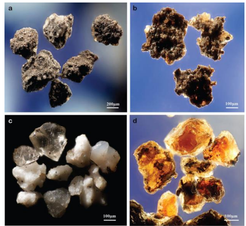
NASAが公開している資料[4]によると、レゴリスは、粒子サイズが40~130μmのシルトで形成されているとのことです。シルト(または沈泥)とは砂と粘土の中間サイズの粒子を指します。レゴリス粒子を顕微鏡で見ると、小さな粒子でもたくさんの角が立った不規則な形状をしています。これにより、月の土壌は空隙率(polosity)が高く、特に地表から10~15cmの深さまではふわふわとした粒子が堆積した状態になっているようです。
またこの不規則な粒子形状が機械的に嚙み合わさるため、レゴリス粒子は圧縮すると凝縮して固まる特性を持ちます。
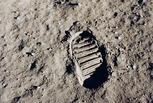
本記事のトップ画にさせていただいている宇宙飛行士が月面へ残した足跡(That's one small step for man)の刻印も、この月の土壌が持つ凝縮する特性によって生まれたものであると言えるでしょう。
レゴリスの材料モデル化
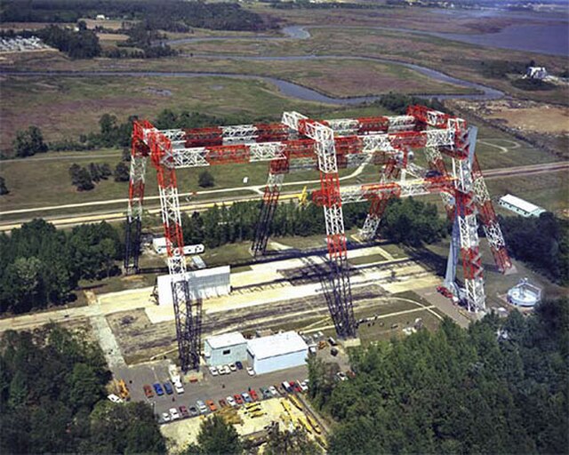
それでは、レゴリスのモデル化を行っていきます。しかしながら、貴重なレゴリスの試験データを入手するのはなかなか難しいです。そこで、ここでは、NASA Langley Research Center (RaRC)の特定のガントリーで着陸土壌として使用されている砂(通称:unwashed sand)の材料特性を使用したいと思います。
この試験設備はアポロ計画の月面着陸実験にも使用された由緒正しい砂です。この砂のサンプルに対して3軸圧縮試験などの複数の試験を実施して得られた材料データが参考文献[5]にてNASA STI programにより公開されています。
解析には、文献[5]で想定されいるのと同じくAnsys LS-DYNA[6]を使用します。LS-DYNAは、落下試験、衝撃および貫通、破壊、衝突などの解析を得意とし、幅広く利用されている陽解法シミュレーションソフトウェアです。
unwashed sandのモデル化にあたり、LS-DYNAが提供する材料モデルの中から、一般に土のモデル化に用いられるMAT5を用いて材料モデルを選択し、使用します。LS-DYNAのmanuralよりMAT5材料モデルの概要を転載すると下記のとおりです。
MAT5 (*MAT_SOIL_AND_FOAM):これは、土壌、コンクリート、または破砕可能な発泡体を表すための比較的単純なマテリアルモデルです。 熱効果が圧力において、体積ひずみの関数として考えられる場合、テーブルを定義できます。
土から泡までを幅広く表現できるとのことなので、レゴリスのふわふわとした粉末のような状態も再現できそうです
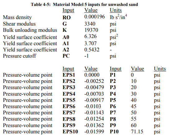
MAT5の材料モデルにおいて、特に重要なパラメータを以下に抜き出します。
RO: 材料質量密度
G: せん断剛性
KUN: 体積弾性率(除荷時のみ用いられる)
A0~A2: 塑性降伏関数に関わる係数
EPS1~10, P1~2: 体積ひずみと圧力の関係を表す曲線を定義
これらの変数に入れる数値次第で、MAT5という材料モデルは、コンクリートや土、泡までを一つのモデルで表現することができます。下記に文献[5]から拝借した、unwashed sandを表すMAT5の入力変数を示します*。
ドロップ試験のシミュレーション
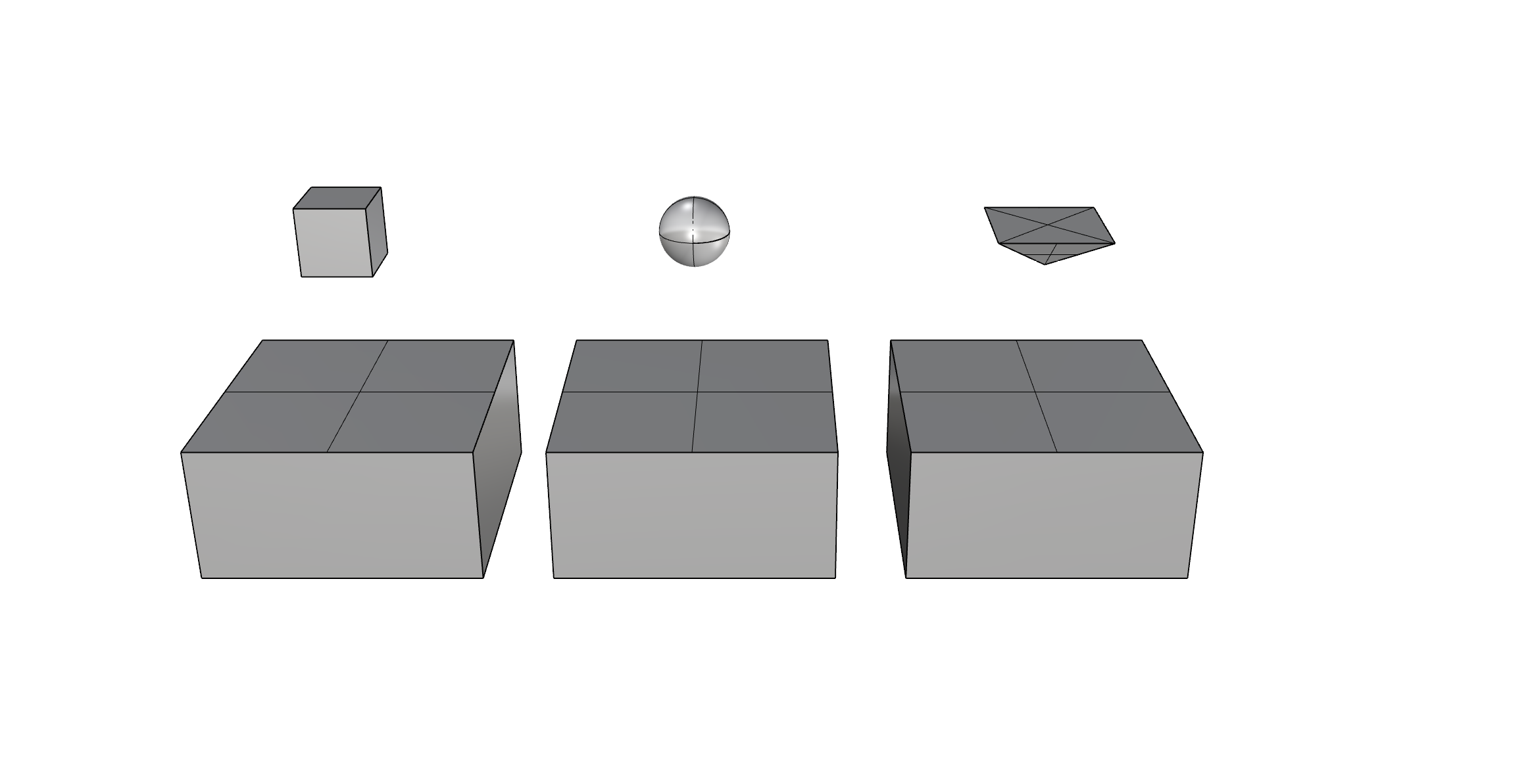
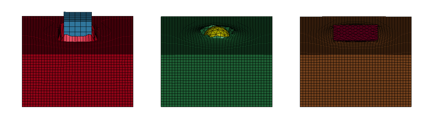
それでは、作成したunwashed sandの材料モデルを地面として、適当な物体を落下させてドロップ試験のシミュレーションをしてみます。落下させる物体として、以下の図に示す(1)cube, (2)sphere, (3)piramidの3つの形状を用意しました。材質は鉄と同じヤング率を持つ弾性体であり、物体の質量はすべて1kgとなるように密度を調整しています。これらを、地球上(重力加速度9.8m/s^2)の環境で、約2mの高さから落とすとどうなるでしょうか?
解析実施 Case01
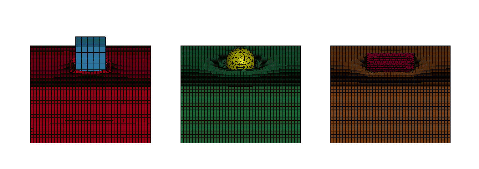
Case01では、unwashed sandそのままの材料モデルを用いて解析をしました。着地後の砂の形状に注目すると、落下物が着地した周囲の砂が盛り上がっています。物体の周りにちょうど隕石が落ちた後のクレーターのような形状が再現されています。クレーターの深さを比べると、(1)<(2)<(3)の順に深くなります。先端がとがっているほど、砂に深く突き刺さる着地をしており、感覚的にも自然な挙動であると判断できます。
解析結果~着地後の姿勢~
解析実施 Case02
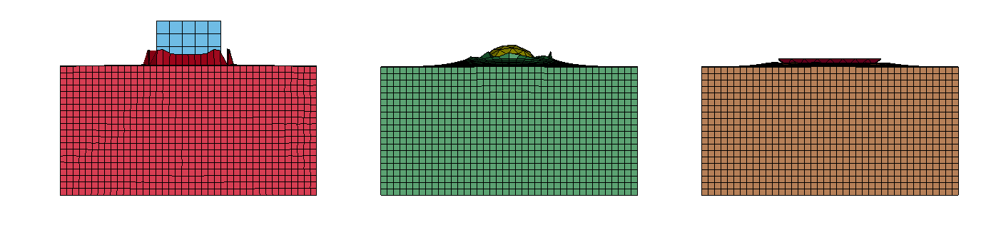
Case02では、着陸における材料特性の影響を観察するため、unwashed sandの入力変数を変更して、せん断剛性Gを1/2にして同じ解析をしてみました。
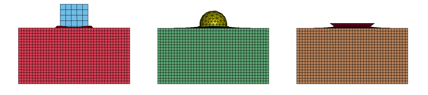
着地後の姿勢を先ほどの結果と比較してみると、どの形状においても、より深く砂の中に埋まっており、生成されたクレーターの盛り上がりも大きくなりました。着地対象の土壌のせん断剛性が低下したために、物体下部の要素が水平方向に逃げやすく、小さな力で移動するために、物体の運動エネルギがゼロになり停止するまでに、より大きく砂要素を変形させたことがうかがえます。
解析結果~着地後の姿勢~
解析結果の数値比較
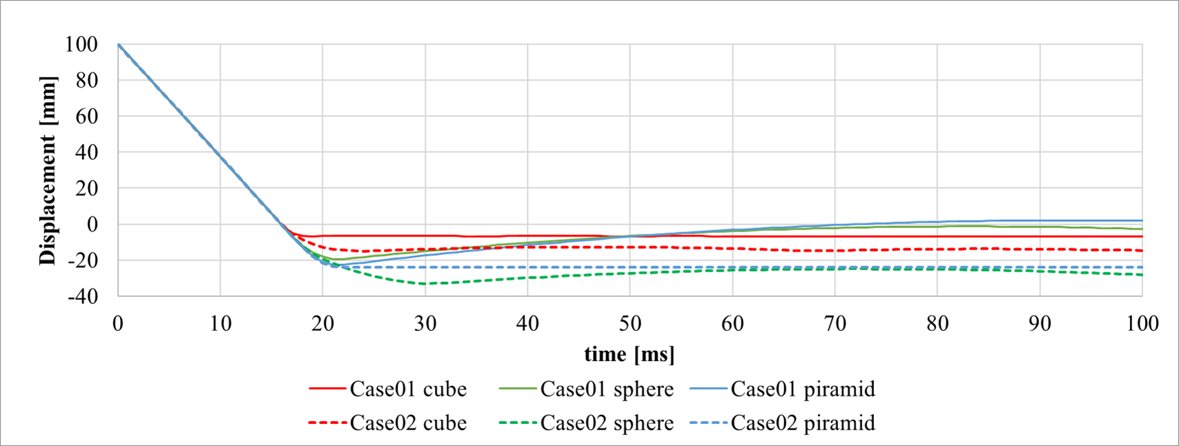
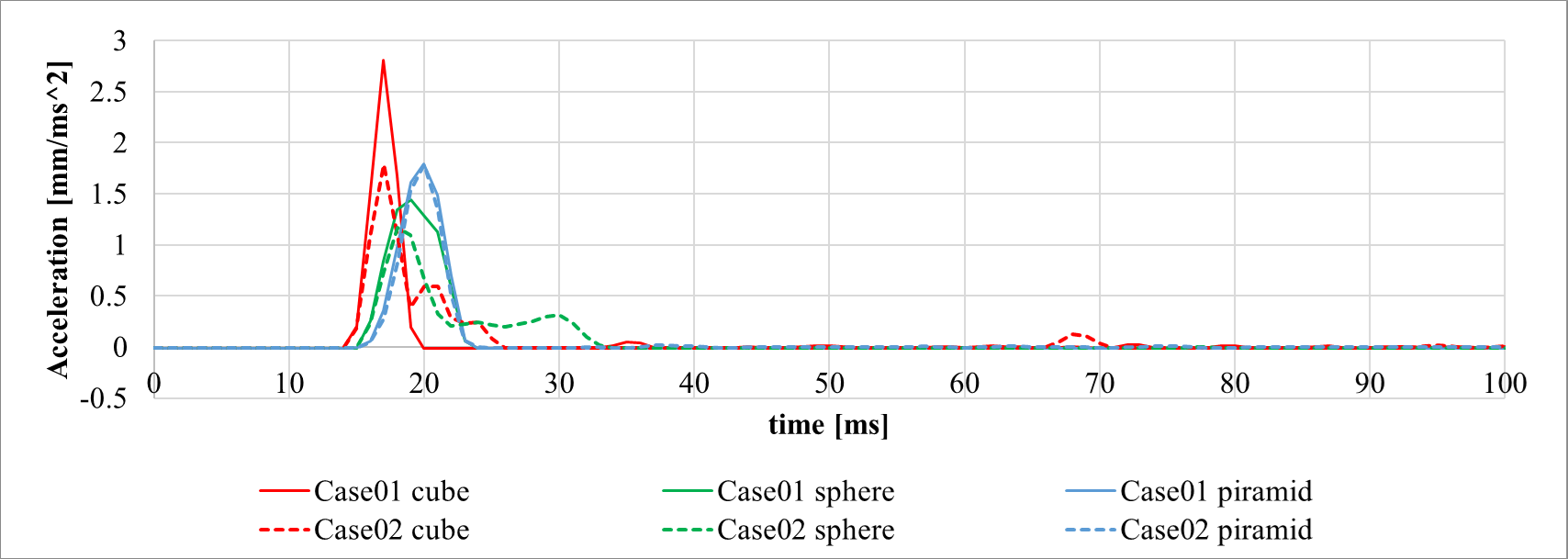
2つの解析結果について、数値により各形状の性能を評価します。ここでは、物体の変位(土壌への侵入量)と衝突時に物体に働く加速度を評価指標として見てみましょう。
下の変位のグラフは、地表の高さを0mmとして、各時間における物体の位置を表しています。これにより、ある速度を持って100mmの高さから下降した物体が、0mmで土壌表面に衝突し、その後どの程度の深さまで侵入して停止するかが分かります。土壌への侵入量としては、Case01, Case02どちらにおいても、(1)cube形状が最も小さい結果となりました。
次に加速度のグラフは、物体が土壌との衝突時に反力から受ける加速度を表しています。14~15msで土壌表面に衝突し、瞬間的に加速度が立ち上がり、ピーク値をとります。特にcase01の条件での(1)cube形状のピーク加速度が大きくなりました。
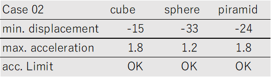
プロットから、最小変位(最大侵入量)と最大加速度を数値にして表にまとめます。
ここで、例えば、着陸物体に対して「搭載機器を保護するために加速度は2000m/s^2以下、そのうえで、なるべく侵入量が小さい形状にしたい」という設計要求があったとします。
すると、Case01の土壌に対しては、(1)cube形状は加速度NGとなるため、加速度OKの形状から侵入量の小さい(2)sphere形状が最適と判断されます。
一方で、Case02の土壌の場合は、どの形状でも加速度OKとなるため侵入量の小さい(1)cube形状が最適という結果になります。
このように、土壌の材料モデルの違いにより、設計要求に対して最適な設計結果は別の形状となりました。
変位の時刻歴
加速度の時刻歴
解析case毎の変位/加速度ピーク値評価

おわりに
実際の設計課題では、複雑な形状と設計要求、多数の制約条件に対して、膨大な解析検討を実施します。その結果出てきた最適な形状の信頼性を担保するためには、現実を的確に表現する材料モデルが構築されていることが大変重要なことが分かります。
当然のことですが、常に現実の物理現象、実験結果と解析結果のコリレーションをとりながら、その現象を表現するに足る材料モデルを使用できているかに注意し、気を配ることが重要です。
砂のモデル一つをとっても、このように現象が再現され、納得のいく挙動をとると大変面白いですね。
本記事の内容はあくまで趣味的検討であり、実際の月面環境を正確に表していません。特に重力加速度の違いは、物体の運動だけでなく、材料特性に影響を与える可能性があります。貴重なデータを公開してくれているNASA STI programの活動に敬意を表するとともに、このように材料モデルについて情報共有、共通認識が取れていることが、CAEを用いた構造設計において重要な基盤であると再確認する取り組みになりました。
※本記事では、一部にWikimedia Commons[7]の画像を使用させていただいております。
参考
[1] JAXA | 小型月着陸実証機(SLIM)の月面着陸の結果・成果等について
[2]開発・運用状況 | 小型月着陸実証機 SLIM | ISAS/JAXA
[3]How to test a Moon landing from Earth (nature.com)
[4]Final IEEE paper formatted footnote added.pdf (nasa.gov)
[5]NASA Constitutive Properties - Gantry, KSC.doc
Introduction
In January 2024, news was reported of the landing of the Smart Lander for Investigating the Moon (SLIM), a small lunar landing demonstration vehicle developed by the Japan Aerospace Exploration Agency (JAXA). According to the report, while it successfully achieved its main mission objective of a 100-meter precision pinpoint landing, the stopping posture after landing was poor, making it difficult to generate power from the solar panels [1][2].
For landing on the Moon, verification through drop tests and numerical analysis on actual equipment is repeatedly conducted, along with the development of shock-absorbing components.
Currently, not only space agencies of various countries but also private companies are aiming at the Moon for various purposes such as research and commercialization. As the first step in lunar utilization, safe landing on lunar soil must be a very interesting topic for many people [3].
In this article, we will try to create the necessary material model for numerical analysis of Lunar Soil (Regolith), the impact object in the landing, and discuss the impact of drop tests simulating the landing on the impact analysis.
Lunar soil (regolith)
First, let's review general knowledge about lunar soils. In planetary science, the sedimentary layers distributed on the surface of the Moon, planets, asteroids, and other celestial bodies are called regolith. Hereafter in this article, the particles that form the soil on the lunar surface will be referred to as regolith.
According to data published by NASA [4], the regolith is formed of silt with a particle size of 40~130 μm. Silt (or silt) refers to particles that are intermediate in size between sand and clay. When regolith particles are viewed under a microscope, even the smallest particles have an irregular shape with many angles. This makes lunar soils appear to have a high polosity, especially at depths of 10-15 cm below the surface, where fluffy particles are deposited.
When regolith particles are compressed, these irregular particle shapes mechanically mesh together, and lunar soil has the property of condensing and solidifying.
The imprint of the astronauts' That's one small step for man on the moon's surface, which is used as the top picture of this article, was also caused by the condensing properties of lunar soil.

Material modeling of regolith
Now we will go on to model regolith. However, it is quite difficult to obtain valuable regolith test data. Therefore, we would like to use the material properties of sand (commonly known as unwashed sand) used as landing soil in a particular gantry at the NASA Langley Research Center (RaRC).
This test facility is a venerable sand that was used in the Apollo program's lunar landing experiments. Material data obtained from several tests on samples of this sand, including triaxial compression tests, have been published by the NASA STI program in reference [5].
The analysis will be performed using Ansys LS-DYNA [6], a widely used explicit simulation software that specializes in the analysis of drop tests, impact and penetration, fracture, and impact.
To model unwashed sand, a material model will be selected from among the material models provided by LS-DYNA, MAT5, which is commonly used for soil modeling, will be used. MAT5 (MAT5**)
MAT5 (*MAT_SOIL_AND_FOAM): This is a relatively simple material model for representing soil, concrete, or crushable foam. If thermal effects are considered as a function of volumetric strain at pressure, a table can be defined.
They can represent a wide range of materials from soil to foam, so it is possible to reproduce conditions such as the fluffy powder of regolith!
The most important parameters of the material model of MAT5 are extracted below.
RO: Material mass density
G: Shear stiffness
KUN: volume modulus (used only for unloading)
A0~A2: Coefficients related to plastic yield function
EPS1~10, P1~2: Define curves representing the relationship between volumetric strain and pressure.
Depending on the values you put into these variables, the MAT5 material model can represent concrete, soil, and even foam in a single model. Below are the input variables for MAT5 representing unwashed sand, borrowed from the literature [5].
Drop test simulation
Now, let's simulate a drop test by dropping an appropriate object onto the *unwashed sand material model that we have created as the ground. We have prepared three shapes of objects to be dropped: (1)cube, (2)sphere, and (3)piramid as shown in the figure below. The material is an elastic material with the same Young's modulus as iron, and the density is adjusted so that all objects have a mass of 1 kg. What will happen if these objects are dropped from a height of about 2m in an environment on earth (gravitational acceleration 9.8m/s^2)?
Analysis performed Case01
In Case01, the material model of unwashed sand was used. If you look at the shape of the sand after the object landed, you will see that the sand around the object is raised. The shape of the crater** around the object is just like the shape of a crater after a meteorite falls. Comparing the depths of the craters, (1)<(2)<(3) are deeper in that order. The more pointed the tip is, the deeper into the sand the landing is, which can be judged to be a natural behavior from a sensory point of view.
Analysis results - posture after landing
Analysis performed Case02
In Case02, to observe the effect of material properties on the landing, the same analysis was performed by changing the input variable for *unwashed sand and setting the shear stiffness G to 1/2.
Comparing the post-landing posture with the previous results, we see that in all geometries, the material is buried deeper in the sand and the raised craters generated are also larger. The reduced shear stiffness of the soil** to be landed on suggests that the elements below the object were able to escape more easily in the horizontal direction and move with less force, causing greater deformation of the sand elements before the kinetic energy of the object was reduced to zero and it came to a stop.
Analysis Results - Post-landing Attitude
Numerical Comparison of Analysis Results
For the two analysis results, we evaluate the performance of each geometry by numerical values. Let's look at the displacement of the object (the amount of penetration into the soil) and the acceleration acting on the object at the time of impact as evaluation indices.
The displacement graph below shows the position of the object at each time, with the height of the ground surface as 0 mm. It shows how an object descending from a height of 100 mm with a certain velocity will impact the soil surface at 0 mm and then how deep it will penetrate to stop. In both Case01 and Case02, the (1) cube shape resulted in the smallest amount of penetration into the soil.
Next, the acceleration graph** shows the acceleration of the object from the reaction force upon impact with the soil. 14~15ms after impacting the soil surface, the acceleration rises instantaneously to a peak value. The peak acceleration is particularly large for the (1)cube shape under the conditions of case01.
From the plot, the minimum displacement (maximum penetration) and maximum acceleration are tabulated numerically.
Let us assume, for example, that there is a design requirement for a landing object that the acceleration should be less than 2000 m/s^2 to protect the onboard equipment, and that the intrusion should be as small as possible.
For the soil in Case 01, the cube shape (1) is not suitable for the acceleration, and the sphere shape (2) is judged to be the best shape for the soil in Case 02, because it has a smaller penetration volume than the cube shape.
On the other hand, in the case of the soil in Case 02, the (1)cube shape with a small amount of intrusion is judged to be optimal because acceleration is OK for any shape.
Thus, due to the difference in the material model of the soil, the optimal design result for the design requirement is a different shape**.
Time history of displacement
Time history of acceleration
Conclusion
In actual design tasks, a vast amount of analytical studies are conducted to determine the complex geometry, design requirements, and numerous constraints. In order to ensure the reliability of the resulting optimal shape, it is very important to have a material model that accurately represents reality.
Naturally, it is important to always pay attention to whether the material model is sufficient to represent the actual physical phenomenon, while correlating the experimental results with the analytical results.
It is very interesting when a sand model reproduces the phenomenon and behaves in a satisfactory manner.
The content of this article is only a hobbyist study and does not accurately represent the actual lunar environment. In particular, differences in gravitational acceleration can affect material properties as well as the motion of objects. I would like to express my respect for the activities of the NASA STI program, which has made valuable data available to the public, and to reaffirm that this kind of information sharing and common understanding of material models is an important foundation for structural design using CAE.
This article uses some images from Wikimedia Commons[7].
Reference.
[1]JAXA | Results and Outcomes of the Lunar Landing of the Small Lunar Module (SLIM)
[2]Development and Operation Status | Small Lunar Module SLIM | ISAS/JAXA
[3]How to test a Moon landing from Earth (nature.com)
[4]Final IEEE paper formatted footnote added.pdf (nasa.gov)
[5]NASA Constitutive Properties - Gantry, KSC.doc
