
タワーのおもしろさ
辞書を開いてみるとタワーには以下の記載がある。
タワー:〘名〙 (tower) 塔。特に、展望台などのある観光用の塔。精選版 日本国語大辞典より
馬鹿と煙はなんとやらの例に漏れず,私は旅先のタワーに必ず登る。景色を一望出来ることも良いのだが,各タワーの特異な架構に目を奪われる。景色を見ずに架構に見とれていることもしばしばある。眺望を確保するためには高さは高い方が良い。ただ高くなっていくと自重が大きくなり地震力が増加したり,強風時の設計用風速が増えることにより風荷重が増大したりする。それらの厳しい制約をかいくぐり各地のタワーは存在している。
今回は国内の3つの展望施設を有する構造物をピックアップし,それぞれ高層の架構を成り立たせている工夫や種々の構造性能を担保する架構特性を解説していく。
お品書き
東京タワー
東京タワーは昭和30年頃,テレビ放送の普及に伴い複数社のアンテナを一箇所にまとめる支持鉄塔として計画された。
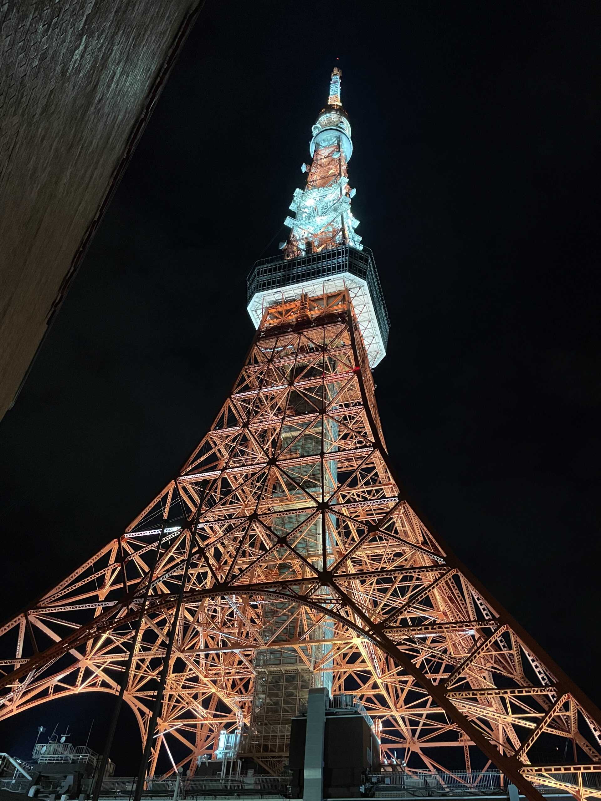
見上げ斜めより
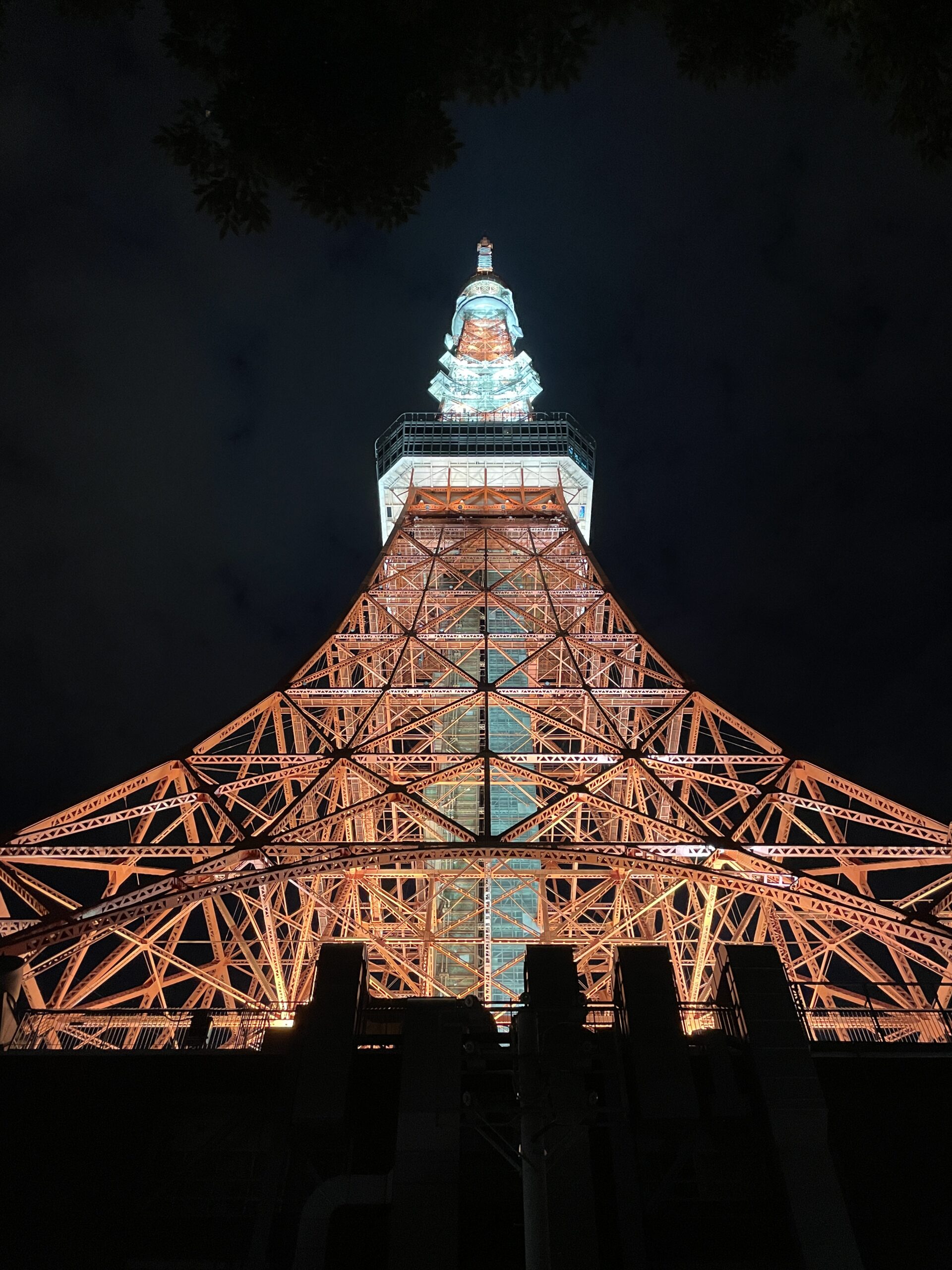
見上げ正面より
| 所在地 | 東京都港区 |
|---|---|
| 竣工年 | 1958年 |
| 設計 | 内藤多仲,日建設計 |
| 施工 | 竹中工務店 |
| 高さ | 333m |
| 構造 | 鉄骨組み立てトラス構造 |
構造設計者の内藤多仲は建築構造の大家で,建築構造における耐震壁の概念を発明し自身の設計する建物に実装して世の中に広めていった人物である。
タワーは253mの鉄塔の上に80mのアンテナ支持塔を載せた333mの電波送受信塔である。タワー足元は80m x 80m程度の矩形でアスペクト比は約4.2と足元でスタンスをしっかり確保している。
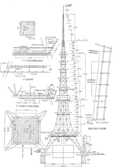
タワー全体構成
構造躯体は形鋼(山形鋼,溝形鋼)と鉄板からなる組み立て材で,部材相互をリベットにて締結してトラス状の主架構を構成している。
よくよく観察してみると同じ組み立て材でもウェブ部分の構成が変わっていて面白い。恐らく支点間距離によって分けていると考えられる。支点間距離が長い部材は地震時の面外変形を抑えるためにラチス状に配置し,短い部材はフィーレンディール状に配置することでウェブ部材接合の簡素化を測っていると考えられる。
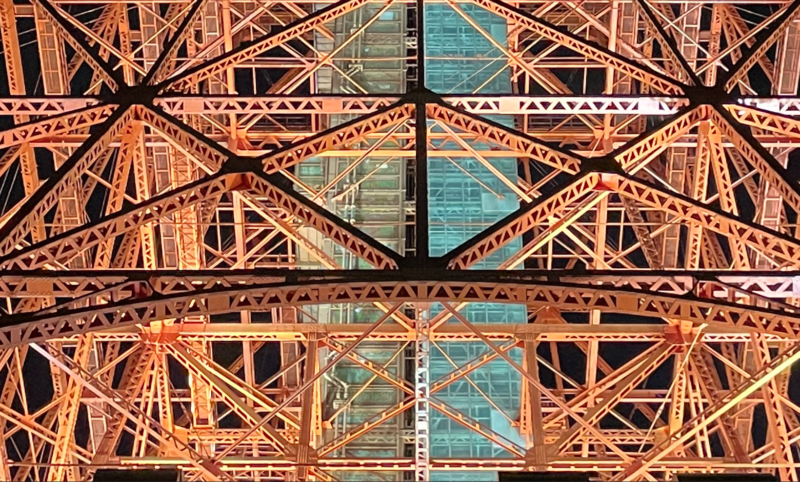
ウェブがラチス状の組立部材
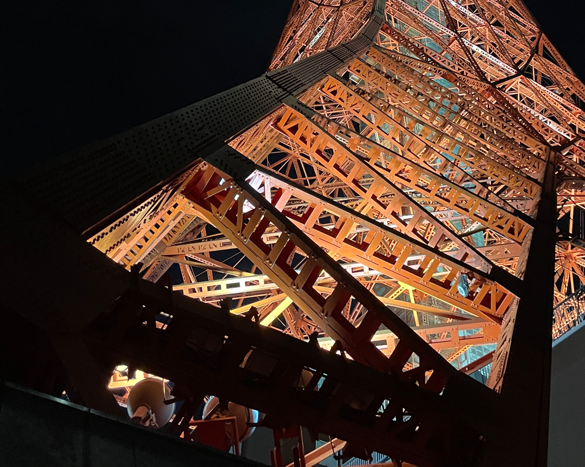
ウェブがフィーレンディール状の組立部材
地上構造物の水平力に対する設計に対して主要な荷重は地震荷重と風荷重である。世の中の大部分の建物は風荷重に比して地震荷重のほうが支配的なため風荷重に対する設計は省略することが多々ある。しかし東京タワーにおいては風荷重が支配的で風速90m/sで水平力に対する設計が行われている。
設計当時はまだ手回しの計算機すら普及しておらず,応力の計算に関しては計算尺が用いられた。主にクレモナ図解法とカスティリアーノ定理が用いられ部材断面が決められていったそう。現代では計算機が普及しているおかげでお手軽に構造解析が回せるので便利である。
以下に東京タワー1構面を平面にモデル化した解析結果を示す。簡易的に風荷重が均等分布するとして静的解析を行っている。タワー上部のせん断力はX形に配されたブレースによりタワー下部に流れる。タワー下部は上部から伝達されたせん断力を地上部のアーチ架構により軸力に変換し基礎に流している。タワーを根源的に見れば地球を支持点とした片持架構のであるため地上部で末広がりの形状を持つことは曲げモーメントの偶力を処理する上でとても合理的である。また風荷重が支配的なためタワー上部を絞って架構上部の投影断面積を減らすことは応力減少に有効に寄与すると考えられる。
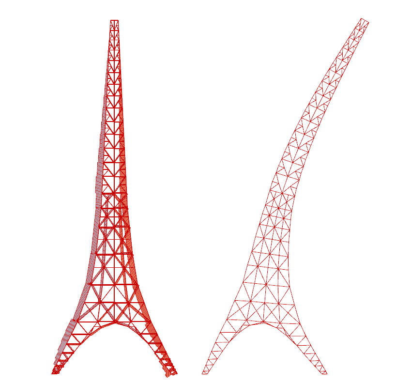
左:風荷重時軸力図,右:風荷重時変位図
参考文献
1)宮地技報No.28 : https://www.miyaji-eng.co.jp/technology/newsletter/media/28/no28-p064-070.pdf
2)田中弥寿雄:東京タワーとエッフェル塔,建築雑誌1990 年10月号,日本建築学会,1990年
京都タワー
京都タワーは高さ30mの建築物の上に100mのタワーが乗っている特殊な架構形態をしている。
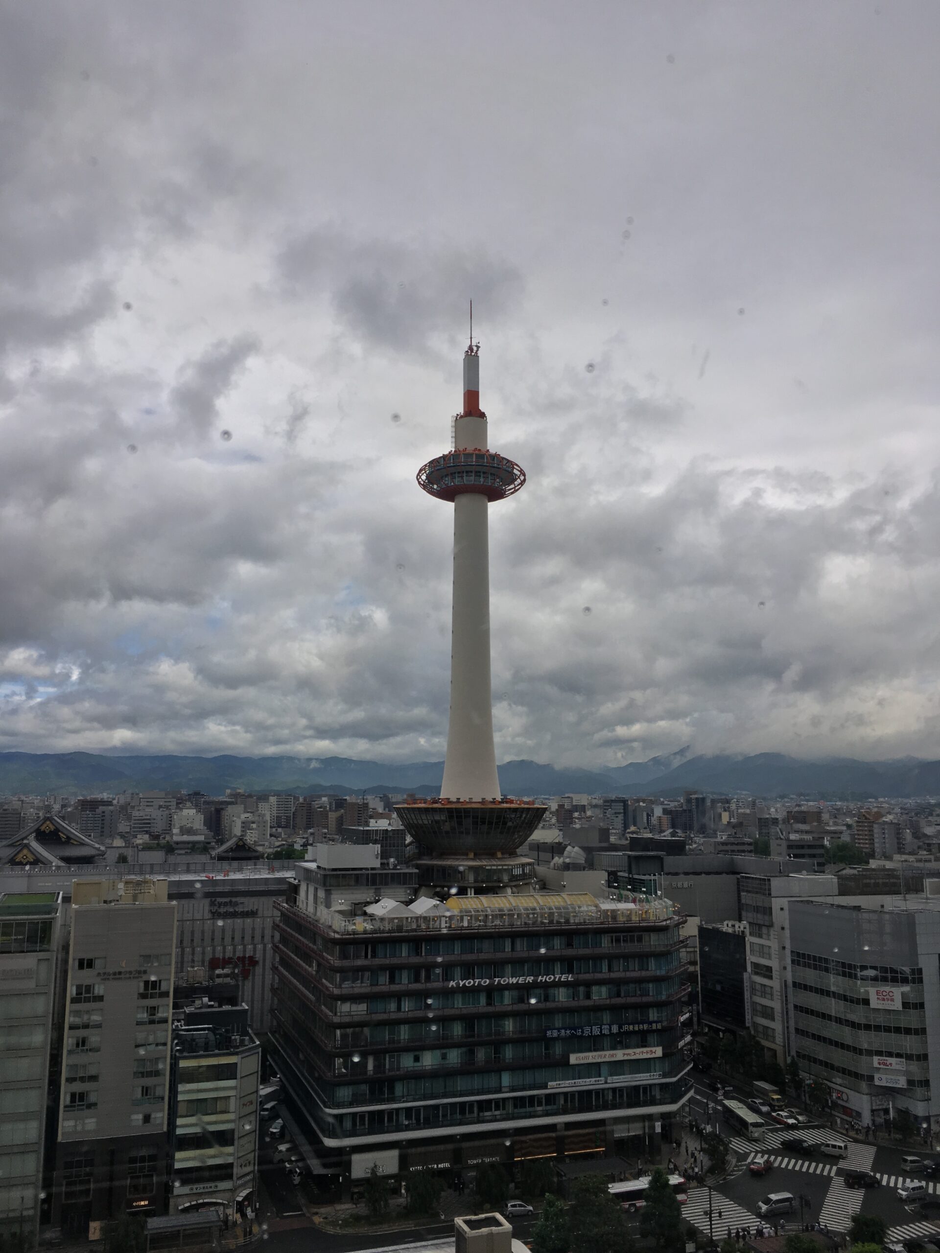
全景昼景
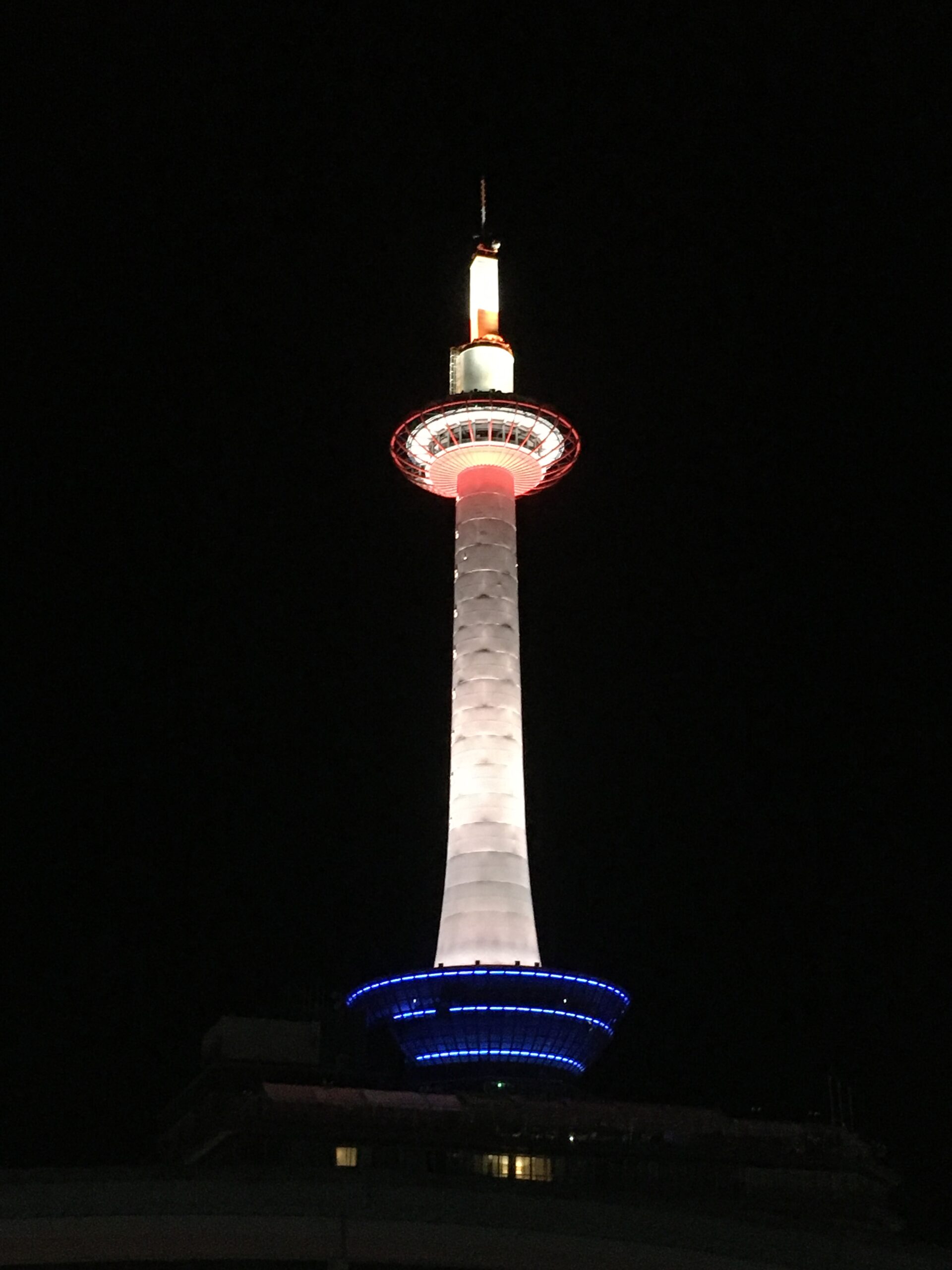
全景夜景
| 竣工年 | 1964年 |
|---|---|
| 意匠設計 | 山田守 |
| 構造設計 | 槻橋諒 |
| 施工 | 大林組 |
| 高さ | 131m |
| 構造 | 下部:鉄骨ラーメン構造 上部:鉄骨モノコック構造 |
| 所在地 | 京都府京都市下京区 |
この建築物はビル部分とタワー部分で構造形式が大きく変わっている。下部構造は鉄骨のラーメ構造であるのに対し,上部タワー構造はモノコック構造(応力外皮膜構造)になっている。モノコック構造はt12~22mmの鋼板で構成されており,局部座屈を防止するために内側にリブプレートが配されている。上にある夜景写真を見ると分かり易いが,鋼板は運搬のため高さ2.7mで輪切りにされ円周方向に4分割されて制作されている。これらの部材を現場溶接にて一体化されている。
構造躯体の様子は展望台部分の内部階段付近で見ることが出来るので行ってみると楽しい。ちなみに年2回内部階段を登って展望台に行くイベントが有る模様。体力に自身のある方はぜひ行ってみていただきたい。
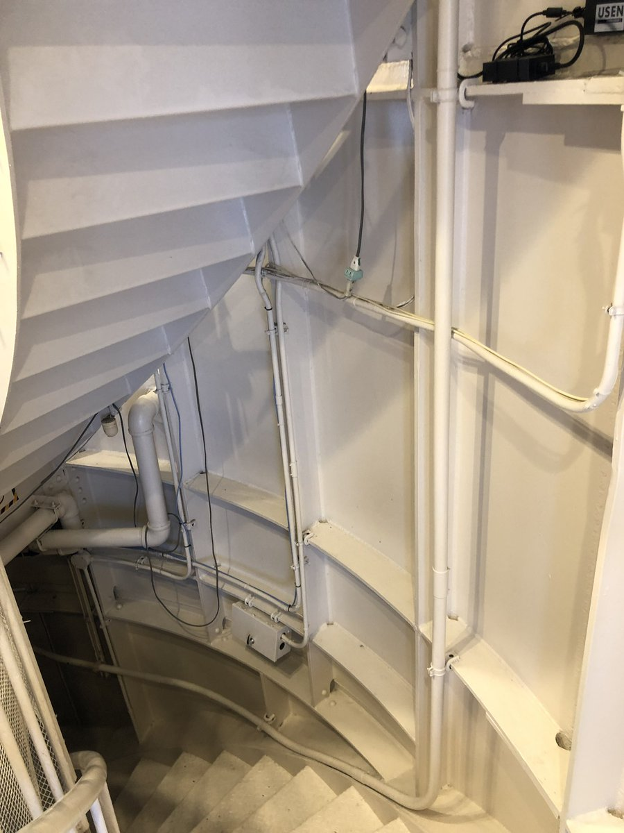
塔内側のリブ:古市渉平氏より
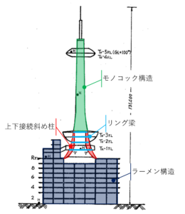
上部モノコック構造と下部ラーメン構造は8本の接続斜め柱により接続されている。さらに接続斜め柱は4本のリング梁により剛に接続されてラーメン架構を形成している。構造形式の異なる架構が接続し応力状態が複雑になることが予想されたため,設計段階で1/120スケールの光弾性実験を行い応力状態を確認して設計を行っている。
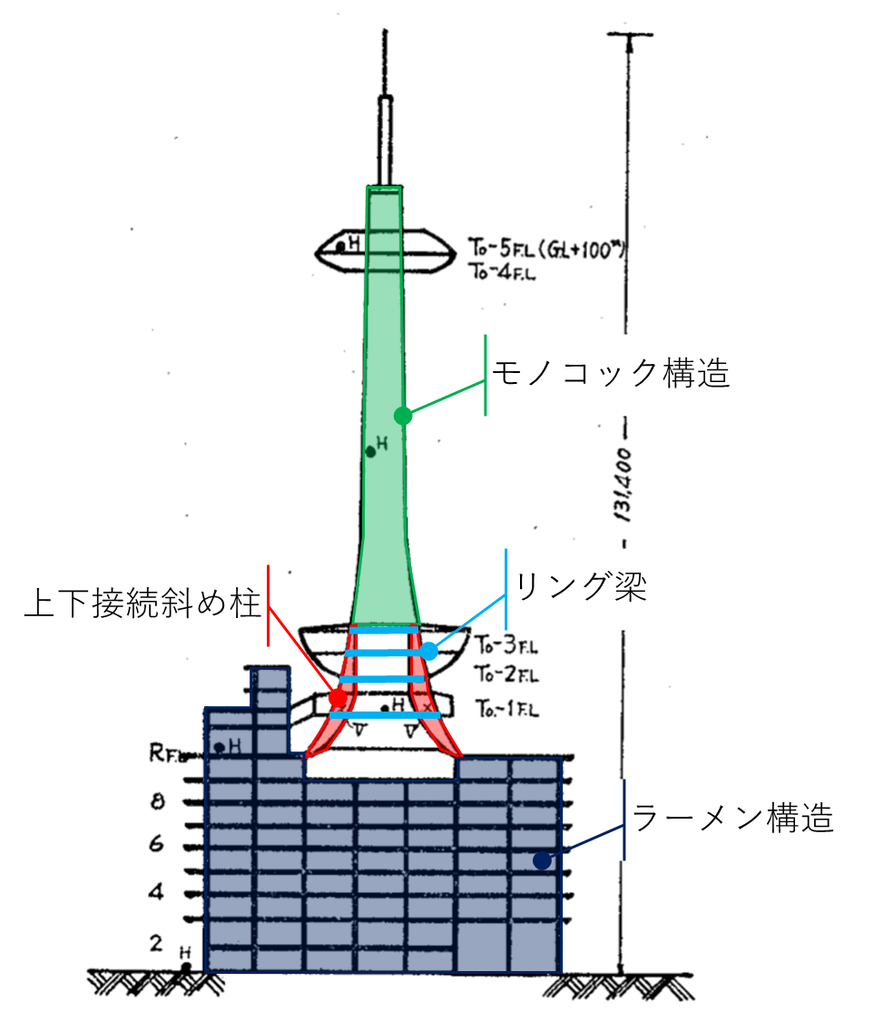
全体構造構成
参考文献
1)棚橋涼:京都タワービル振動実験,日本建築学会論文報告集号外昭和40年9月,1965
2)棚橋涼:京都タワー鋼製模型の静的載荷詩決結果,日本建築学会論文報告集号外昭和40年9月,1965
梅田スカイビル
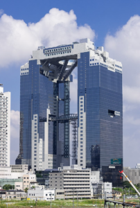
梅田スカイビルはJR大阪駅の北西に位置する超高層ビルで最上階・屋上には展望スペースが存在する。
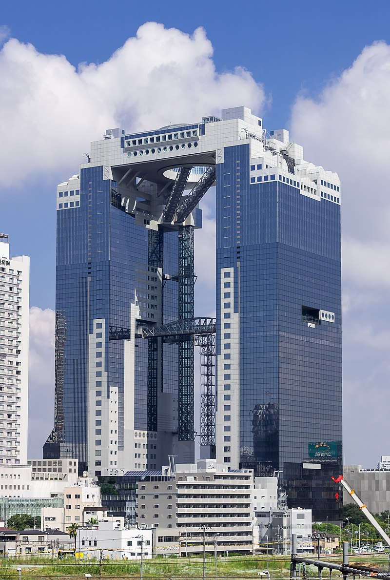
©Kakidai(Licensed under CC BY 4.0)
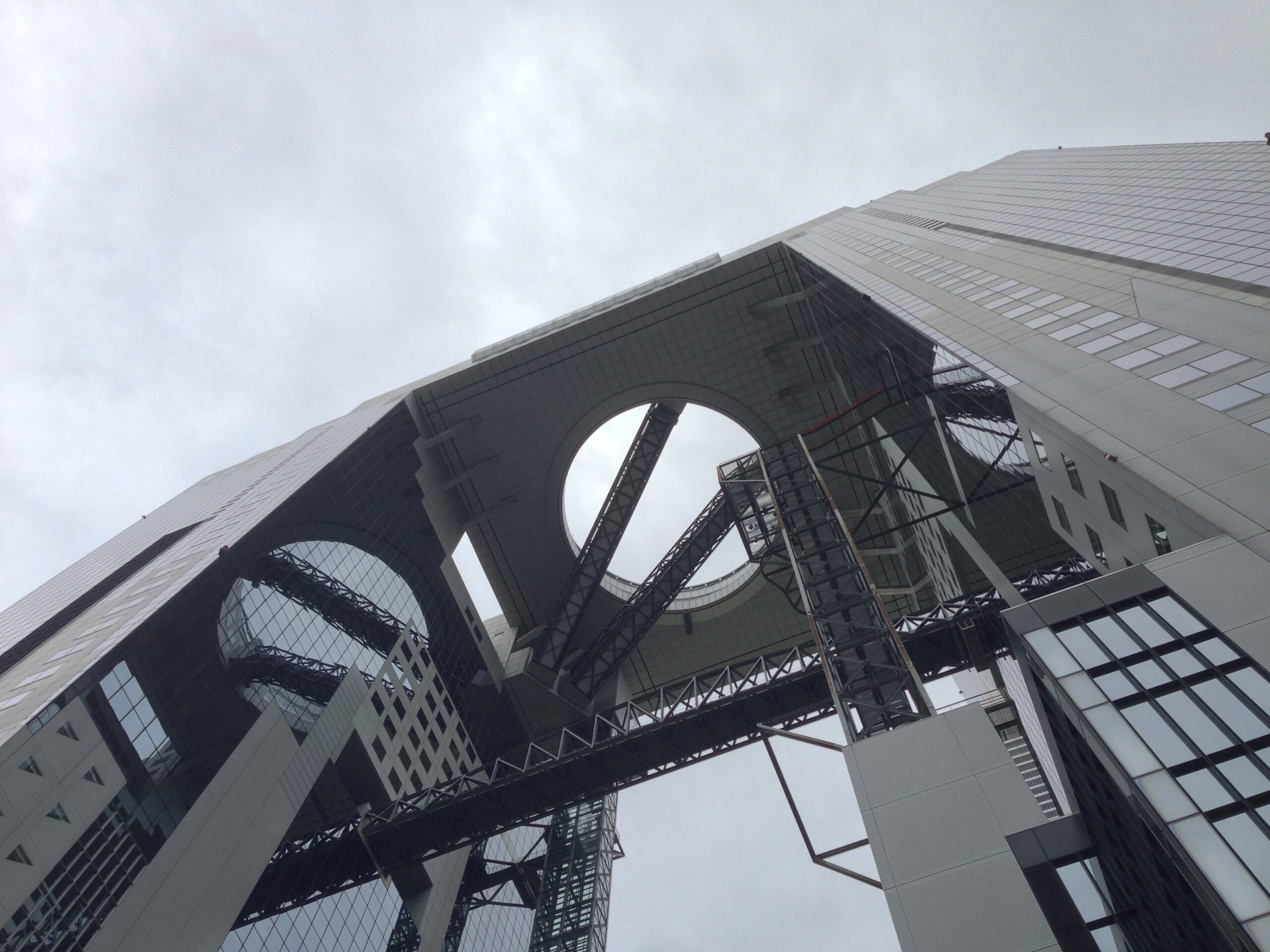
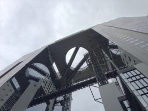
*見上げ*
| 竣工年 | 1993年 |
|---|---|
| 意匠設計 | 原広司 |
| 構造設計 | 木村俊彦 |
| 施工 | 竹中工務店,大林組,鹿島建設,青木建設JV |
| 高さ | 173.05m |
| 構造 | 鉄骨造 |
| 所在地 | 大阪府大阪市北区 |
各棟は54m隔てた2棟からなり,それぞれ幅27m x 奥行き54m の東棟,幅33m x 奥行き54mの西棟,さらにこの両棟を頂部で繋ぐ空中庭園部で構成されている。
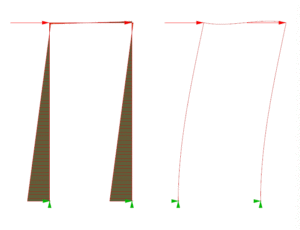
各棟単体のアスペクト比は5.2~6.4程度あり,常時人が居住する事務所用途としては振動による居住障害が懸念される。相互を頂部空中庭園により剛に接続することにより2棟が外力に対し一体となって抵抗し,更に頂部空中庭園架構の曲げ戻し効果により発生応力及び変形が大幅に改善される。以下の図は梅田スカイビルを模した門形架構頂部に集中荷重を掛けている解析である。頂部横架材の断面性能を変化させているが,断面性能の増減により曲げモーメントの増減と水平変位の増減がわかるかと思う。
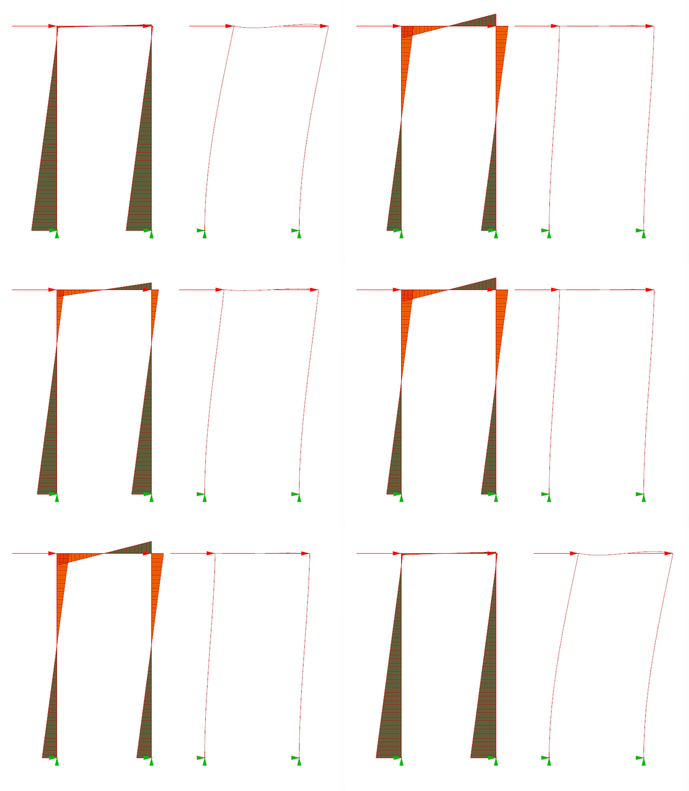
左:曲げモーメント図,右:変位図
54m x 54mの平面を持つ空中庭園の施工方法,当初は頂部から持ち送り方式で各棟から半分ずつ部材を出し中央で連結する方法を想定していた。しかし持ち送り方式の場合空中での作業が多くなり吊り足場などの特殊工が必要になってくる。そのような状況から施工合理化のためリフトアップ工法が立案された。空中庭園部材を地上で地組みし,それを所定の位置まで釣り上げる方法である。リフトアップ当日,空中庭園は約7時間で所定の高さまで釣り上がり東西棟と連結された。圧倒的スピードである。
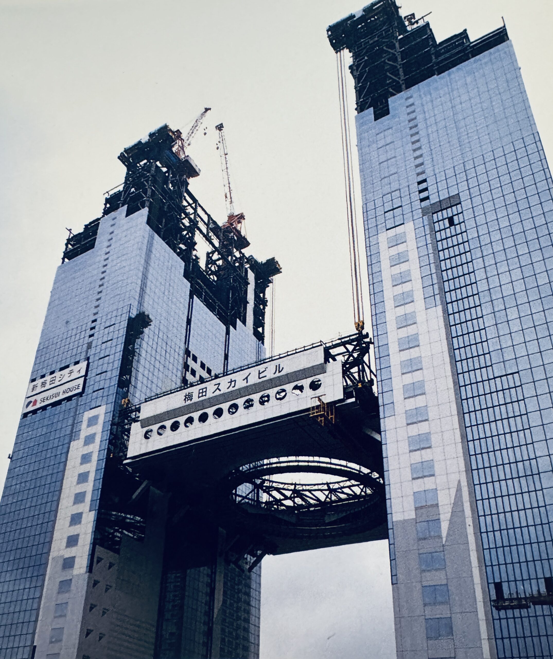
*リフトアップ状況 1)より
参考文献
1)新建築社:日本現代建築家シリーズ⑰木村俊彦,1996年
まとめ
今回は国内の展望施設を有する建築物を紹介しました。構造物が高くなるに連れて荷重は増え,応答も増え設計者はどうにかせねばと頭を抱えます。しかしながらその制約を満たすための構造的工夫で特異的な形態になることが,都市ランドマークとしてのアドバンテージになっているのがとてもおもしろいです。
今度のお休みはどこかの展望台に登ってみてはいかがでしょうか?できれば景色だけでなく,背後の構造架構にも思いを馳せていただければ幸いです。
Interest of the Tower
Opening the dictionary, the tower has the following entry.
Tower: 〘name〙 (tower) A tower. Especially, a tower for sightseeing with an observatory. From the Japanese Language Dictionary (Seisen-ban)
As usual, I always climb towers when I travel. The panoramic view is one thing, but the unique structure of each tower is what catches my attention. I often find myself gazing at the structure without looking at the view. The taller the tower, the better the view. However, the higher the tower, the greater its own weight, which increases seismic forces, and the higher the design wind speed in high winds, which increases wind loads. Towers in various locations have been built to overcome these severe limitations.
In this issue, three structures with observatory facilities in Japan will be selected, and the innovations that make up the high-rise structures and the characteristics of the structures that ensure various structural performances will be explained.
list of articles (e.g. in a magazine)
Structural Dynamics in a Walking Tour 2
Tokyo Tower
Around 1955, Tokyo Tower was planned as a support tower to combine antennas of several companies in one place in response to the spread of television broadcasting.
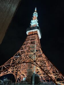
Looking up from an angle
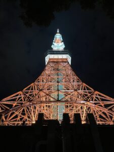
Looking up from the front
| Location | Minato Ward, Tokyo |
|---|---|
| Year Completed | 1958 |
| design | Tatyu Naito,Nikken Sekkei |
| construction | Takenaka Public Works Shop |
| height | 333m |
| structure | Steel-frame assembled truss structure |
The structural designer, Tanaka Naito, is a major architectural structural engineer who invented the concept of earthquake-resistant walls in building structures, implemented it in buildings he designed, and spread it throughout the world.
The tower is a 333-meter radio transmission and reception tower with an 80-meter antenna support tower on top of a 253-meter steel tower. The foot of the tower is a rectangle of about 80m x 80m with an aspect ratio of approximately 4.2, ensuring a firm stance at the foot of the tower.
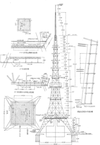
Overall tower configuration
The structural frame is an assembly of steel shapes (flat and channel steel) and steel plates, which are riveted to each other to form the main truss structure.
Upon closer inspection, it is interesting to note that the same assembly material has a different configuration of the web part. It is thought that they are probably divided according to the distance between the fulcrums. It is thought that long members are arranged in a lattice-like configuration to suppress out-of-plane deformation during earthquakes, while short members are arranged in a firendial configuration to simplify the joining of the web members.
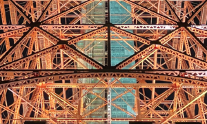
Assembled member with lattice-like web
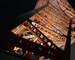
Assembly member with web in the form of a firendial
The primary loads for designing for horizontal forces in above-ground structures are seismic and wind loads. In most buildings in the world, seismic loads are dominant in comparison to wind loads, so the design for wind loads is often omitted. However, wind loads are dominant in the Tokyo Tower, and the horizontal forces are designed for a wind speed of 90 m/s.
At the time of design, even hand-cranked calculators were not yet widely available, and a slide rule was used to calculate stresses. The Cremona method and the Castigliano Theorem were mainly used to determine the cross-sections of the members. Nowadays, it is convenient to perform structural analysis easily thanks to the widespread use of calculators.
Below are the results of an analysis in which the Tokyo Tower 1 structure is modeled as a plane surface. For simplicity, static analysis is performed assuming that wind loads are evenly distributed. Shear forces at the top of the tower are transferred to the bottom of the tower by the X-shaped braces. In the lower part of the tower, the shear force transmitted from the upper part is converted to axial force by the arch structure at the ground level and is transferred to the foundation. Since the tower is fundamentally a cantilever structure with the earth as the support point, it is very reasonable for the tower to have a terminal shape at the ground level to handle the incidental bending moments. In addition, since wind loads are dominant, reducing the projected cross-sectional area at the top of the structure by narrowing the top of the tower is considered to contribute effectively to the reduction of stresses.
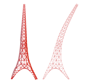
Left: Axis force diagram during wind load, Right: Transformation diagram during wind load.
References
1)Miyachi Technical Journal No.28 : https://www.miyaji-eng.co.jp/technology/newsletter/media/28/no28-p064-070.pdf
2)Toshiya Tanaka: Tokyo Tower and Eiffel Tower, Architectural Magazine, October 1990, Architectural Institute of Japan, 1990
Kyoto Tower
Kyoto Tower has a special form of structure with a 100-meter tower on top of a 30-meter-high structure.
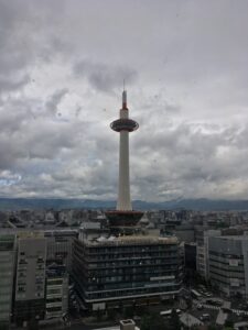
Panoramic daytime view
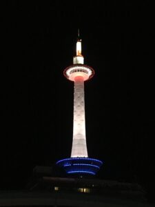
Panoramic night view
| Year Completed | 1964 | |
|---|---|---|
| design | guardian of Yamada | |
| Structural Design | Ryo Tsukihashi | |
| construction | Obayashi Corporation | |
| Height | 131m | Structure |
| Structure | Lower part: Steel Rahmen Structure Upper part: Steel Monocoque Structure | |
| Location | Shimogyo-ku, Kyoto City, Kyoto Prefecture |
The structural form of this building is significantly different between the building and tower sections. The lower structure is a steel frame rame structure, while the upper tower structure is a monocoque structure (stress outer skin membrane structure). The monocoque structure is made of steel plates of 12 to 22 mm in thickness, and rib plates are placed inside to prevent local buckling. As can be easily seen in the night view photo above, the steel plates are cut into rings at a height of 2.7 m for transportation and divided into four sections in the circumferential direction. These parts were welded together on site.
It is fun to visit the observatory to see the structural framework near the internal staircase. Incidentally, there seems to be an event twice a year where visitors climb the internal stairs to the observation deck. If you are physically fit, you should definitely try it.
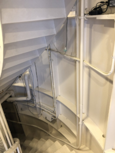
塔Inner rib: from Shohei Furuichi
The upper monocoque structure and the lower ramen structure are connected by eight connecting diagonal columns. Furthermore, the connected diagonal columns are rigidly connected by four ring beams to form a rigid-frame structure. Since it was anticipated that the stress state would be complicated due to the connection of structures of different types, a 1/120-scale photoelastic experiment was conducted in the design stage to confirm the stress state.
Overall structural configuration
References
1)Ryo Tanahashi: Kyoto Tower Building Vibration Experiment, Transactions of the Architectural Institute of Japan, September 1965, 1965.
2)R. Tanahashi: Static Loading Poetic Decision Result of the Steel Model of Kyoto Tower, Transactions of the Architectural Institute of Japan, September 1965, 1965
Umeda Sky Building
The Umeda Sky Building is a skyscraper located northwest of JR Osaka Station with an observation deck on the top floor and roof.
©Kakidai(Licensed under CC BY 4.0)
*looking up*
| Year of Completion | 1993 |
|---|---|
| Hara Hiroshi | TOSHIHIKO KIMURA |
| Structural Design | KIMURA Toshihiko |
| Construction | Takenaka Public Works, Ohayashi Group, Kashima Construction, Aoki Construction JV |
| TAKANAKA Kobayashi, Kashima Kobayashi, Aoki Kobayashi JV - - Construction | |
| Constructions | Iron Bone Construction |
| Location | Osaka City, Osaka Kita-ku |
Each building consists of two wings separated by 54 m, the east wing measuring 27 m wide by 54 m deep, the west wing measuring 33 m wide by 54 m deep, and a hanging garden connecting the two wings at the top.
The aspect ratio of each building is about 5.2 to 6.4, and there is a concern that the buildings may cause vibration problems for office use, where people are always in residence. By connecting the two buildings rigidly with each other by the roof garden, the two buildings resist external forces as a whole, and the bending back effect of the roof garden structure significantly improves the generated stresses and deformations. The following figure shows an analysis of the concentrated load applied to the apex of a gabled girder structure, which is modeled after the Umeda Sky Building. The cross-sectional performance of the top spanner is varied, and you can see the increase or decrease in bending moment and horizontal displacement as the cross-sectional performance is increased or decreased.
Left: Bending moment diagram, Right: Displacement diagram
The original plan called for the construction of a 54m x 54m hanging garden, with half of the members from each building being taken out from the top and joined together in the center. However, this method requires a lot of work in the air and special construction equipment, such as suspended scaffolding, is needed. Under these circumstances, the lift-up method was proposed to rationalize the construction. In this method, the hanging garden components are assembled on the ground and then fished up to a predetermined position. On the day of the lift-up, the hanging garden was raised to the specified height and connected to the east and west wings in about 7 hours. The speed was overwhelmingly fast.
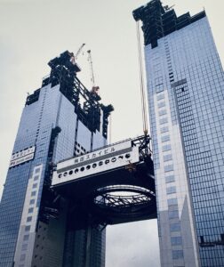
*Lifting status from 1)
参考文献
1)Shinkenchiku-sha: Japan Contemporary Architects Series⑰ Toshihiko Kimura, 1996
Summary.
In this issue, we have introduced buildings with observation facilities in Japan. As structures become taller and taller, the load increases and the response increases, leaving designers with no choice but to do something about it. However, it is very interesting to see how the structural devices used to meet these restrictions have resulted in a unique form, which is an advantage as an urban landmark.
Why don't you climb up to one of the observatories on your next vacation? If possible, I hope you will not only enjoy the view, but also contemplate the structural structure behind it.
