
はじめに
弊社には、幾何学と力学を愛することを共通点として、機械、流体、物理、数学、建築など、多岐にわたる工学分野のバックグラウンドを持つエンジニアが在籍しています。
共通の理論が共通言語のように機能しているものの、各分野で設計する対象物が大きく異なり、構造の思考過程やシステムの違い、各業界の慣習や専門用語など、日々学ぶことが多くとても楽しいです。
そんな弊社の楽しい雰囲気の中でも、建築・土木をバックグラウンドとする構造エンジニアは、対象物が最も大きい建築物や橋梁の構造設計に携わっており、人々が意識せずに日常的に利用しています。
今回はそんな建築・土木の構造エンジニアが、都内に架かる橋梁を例に、どのような視点で構造物を見ているかを記していこうと思います。
おしながき
今回は、都内の以下の4つの橋梁を例に挙げて構造を解説していきたいと思います。
どの橋梁もJR東京駅から電車で30分以内でアクセス可能です。
ちなみに、弊社はJR東京駅から徒歩約25分の場所に位置しています。
1:千代田線荒川橋梁
2:浜松町駅構内跨線人道橋
3:ブリッジ渋谷21
4:新宿駅南口甲州街道歩道橋
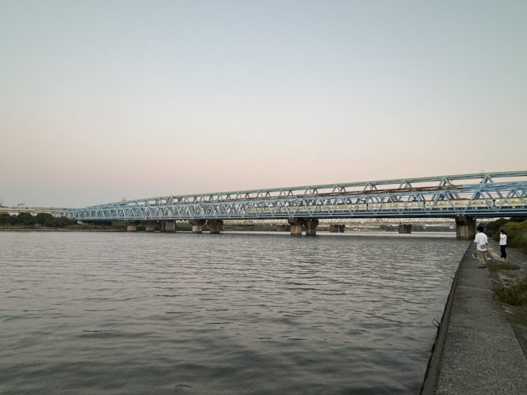
千代田線荒川橋梁:ワーレントラス
建設年:1968年
設計:不明
構造:ワーレントラス
スパン長さ:情報無し
用途:鉄道橋
JR常磐線・東京メトロ千代田線で千葉方面から都内に来る方には、よく目にしているかもしれませんね。
ここにはJR常磐線、東京メトロ千代田線、東武伊勢崎線、つくばエクスプレスの4つの鉄道橋が架かっており、多くが「ワーレントラス」で構成されています。
トラス構造には、プラットトラス、ハウトラスなどさまざまな形状がありますが、ワーレントラスでは中間の鉛直材を省くことにより、鉄骨量を削減し経済性が高く、そのため広く普及しています。
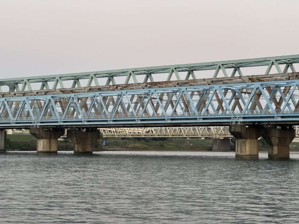
写真ースパン詳細
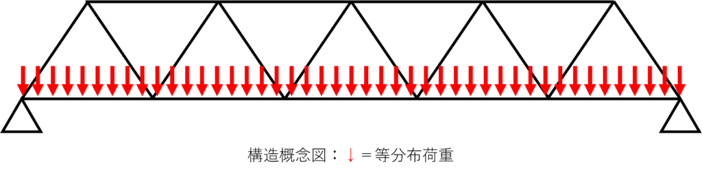
構造をシンプルに表現した概念図を示します。
上下の弦材を結ぶ斜めのラチス材が特徴的な構造形式です。
橋梁下は船舶の通行を考慮しており、そのため下弦材の上にレールが設置されて電車が通行しています。
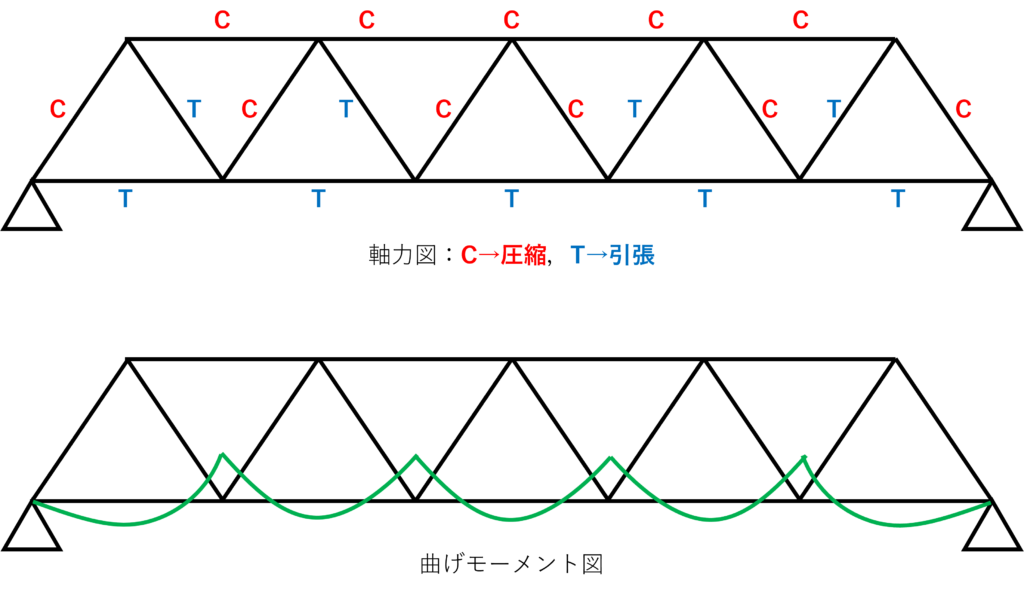
この橋梁の軸力図と曲げモーメント図を記載すると以下のようになります。
基本的に、上弦材は圧縮力を、下弦材は引張力を受け持ちます。その間にあるラチス材は圧縮もしくは引張の両方の力を受けることがあります。
曲げモーメントについては、線路周りの固定荷重や電車の走行荷重が下弦材に作用し、上弦材やラチス材にはほとんど曲げモーメントが生じません。
また、この曲げモーメント図は部材が剛接合されていると仮定していますが、構造上は部材がピン接合されていても機能に影響はありません。
浜松町駅構内跨線人道橋:フィーレンディールトラス
建設年:1984年
設計:日本国有鉄道
構造:フィーレンディールトラス
スパン長さ:約65m
用途:歩道橋
備考:1984年土木学会田中賞
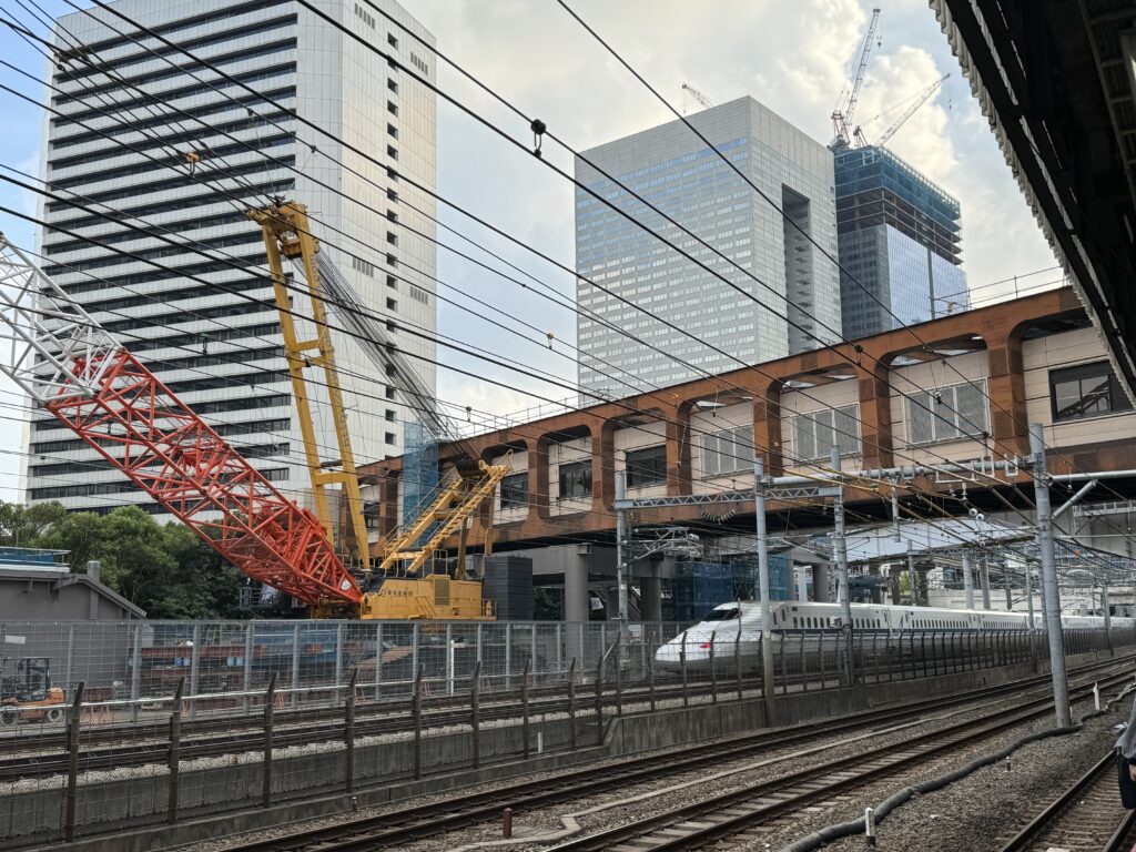
こちらはJR浜松町駅の東側に位置する人道橋です。JR山手線や、羽田空港へ向かう東京モノレールを利用する際には、おそらくご覧になるでしょう。
駅構内と駅東側を、電車・新幹線をまたいで結ぶ重要な橋です。
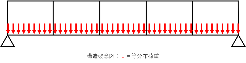
以下にフィーレンディールトラスの構造概念図を示します。
先程のワーレントラスとは異なり、このトラスは水平と鉛直の部材のみで構成されており、斜めの部材がないことが特徴です。また、ワーレントラスとは異なり、このトラスでは各部材が剛接合されていなければ構造が成立しません。
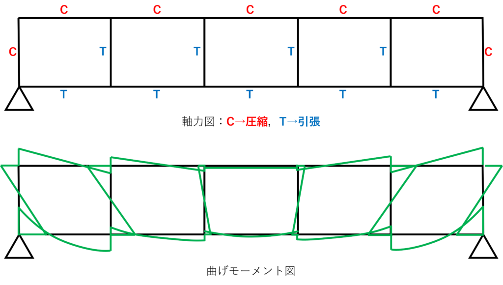
以下に軸力図と曲げモーメント図を示します。
上弦材には圧縮力、下弦材には引張力が作用する状況は変わりませんが、その代わり鉛直部材には大きな曲げモーメントが作用します。これは、ワーレントラスにおいてラチス材が担っていた軸力を鉛直材が負担しているためです。
一般的には、構造部材が軸力を担う方が断面効率が良いため、ワーレントラスやプラットトラスなどのラチス材を用いた方が効率的ですが、浜松町駅構内跨線人道橋では、橋内部が屋内となっており、電車を眺める景観を妨げないためにフィーレンディールトラス形式が採用されたと考えられます。
構造合理性だけではなく、その他の要素も構造形式の決定に影響を与えるのが面白い点です。
ブリッジ渋谷21:トラス形フィーレンディール
建設年:2000年
設計:東急建設株式会社(総合設計)+アーキテクトファイブ(意匠デザイン)
+株式会社梅沢建築構造研究所(構造デザイン)
構造:トラス形フィーレンディール
スパン長さ:50m
用途:歩道橋
備考:2001年度グッドデザイン賞(建築・環境デザイン部門)
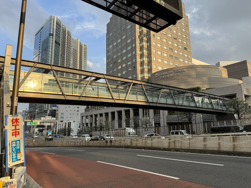
JR渋谷駅の南南口を出て、高速道路に沿って西へ進むとすぐにその歩道橋に出会います。セルリアンタワーのふもとに位置しています。
ちなみに『呪術廻戦』第94話で、虎杖と伏黒はこの歩道橋付近で敵と対峙し、戦闘が始まるシーンがあります。
この歩道橋は、橋梁としては珍しく、建築家と構造家の両方が設計に関わっている点が特徴的な橋です。建築と土木の業界では美学が異なり協力することが少ないため、この橋は珍しい例です。
トラス構造でありがちな部材の集合による無骨さを避け、まるで道路上に浮いているかのような印象を与えます。また、各部材のサイズもフィーレンディールトラスより小さくすることが可能です。
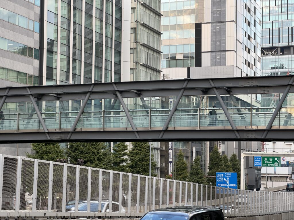
写真ー部分詳細
以下に構造概念図を示します。
最初に登場したワーレントラスとは部材の配置が似ていますが、ラチス材同士が離れて弦材と接合されています。
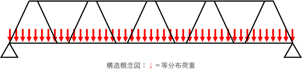
以下に軸力図・曲げモーメント図を示します。
ラチス材の角度に依存しますが、応力の特性はワーレントラスとフィーレンディールトラスの中間に位置し、各部材が軸力と曲げモーメントをバランスよく受け持ちます。
ラチス材の角度を調整することで、部材の応力状態をコントロールし、シルエットを制御することができます。
意匠的な美しさだけでなく構造的な美しさも兼ね備えています。
新宿駅南口甲州街道歩道橋:プラット+フィーレンディールトラス
建設年:1998年
設計:川田工業
構造:プラットトラス+フィーレンディールトラス
スパン長さ:約54m
用途:歩道橋
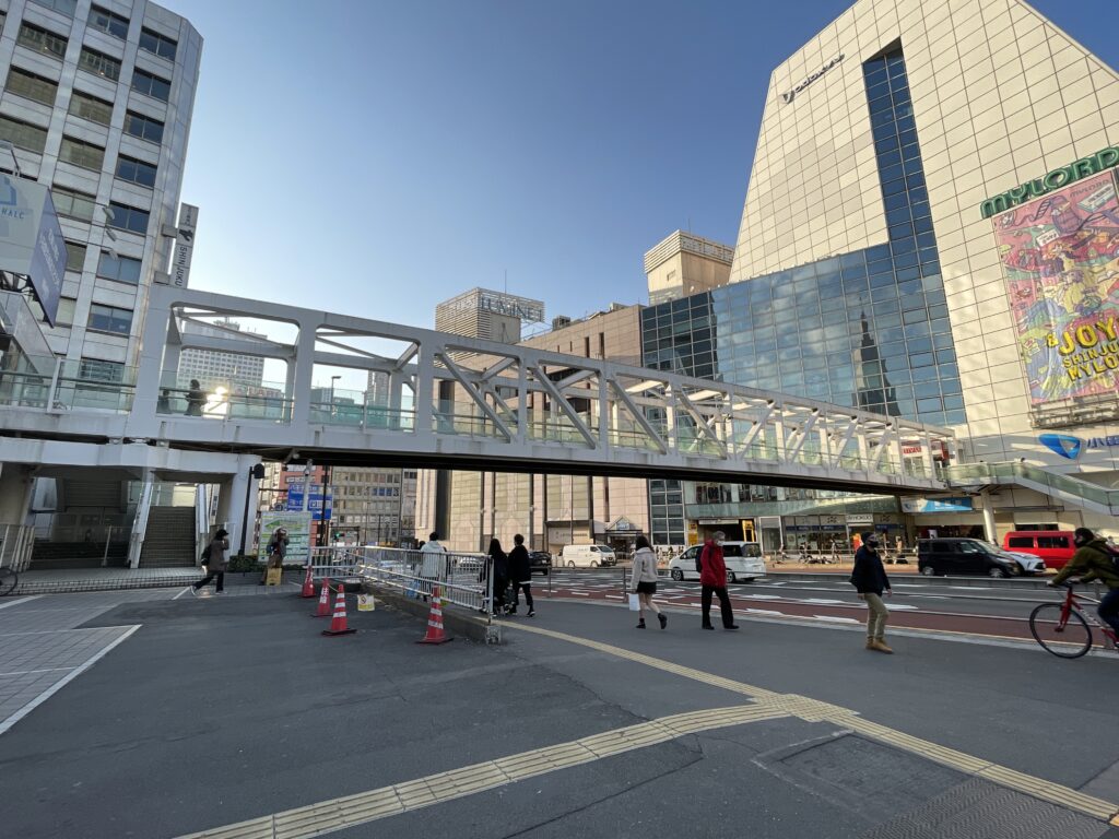
JR新宿駅の南口を出てすぐの西側に位置する歩道橋です。小田急ミロードビルと新宿サザンテラスを結んでいます。
この橋はやや特殊な構造をしており、その形式がどのような経緯で選ばれたのか興味をそそられます。
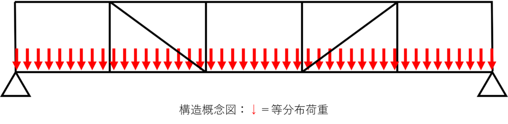
以下に構造概念図を記載します。
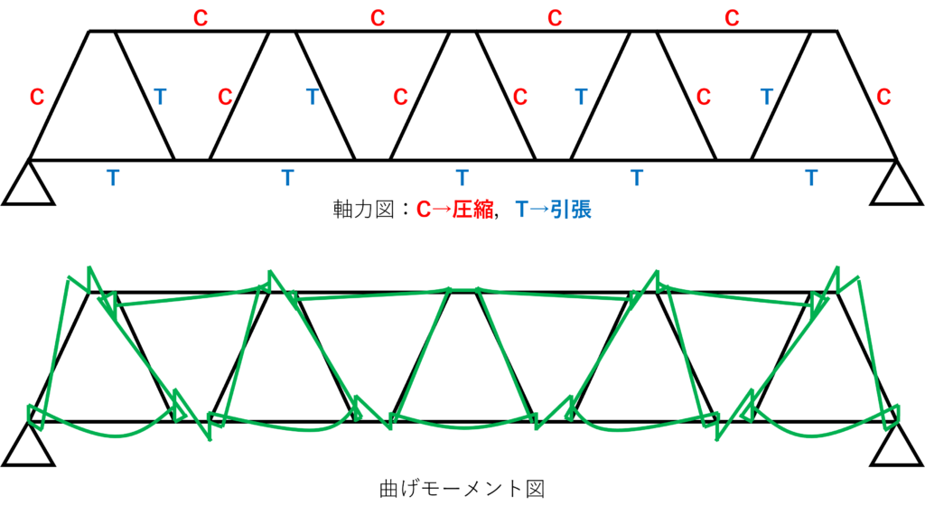
端部にはフィーレンディールトラスを、中央部にはプラットトラスを採用しており、橋の中間で構造形式が変わる設計になっています。
初見では応力状態に応じた構造形式の選定と考えがちですが、実際にはそうではないようです。
以下に軸力図・曲げモーメント図を示します。
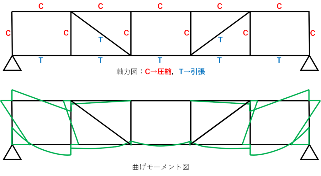
等分布荷重から生じるせん断力は橋端部で大きく、その結果、フィーレンディールトラスの鉛直材が受けるせん断力も端部で大きくなります。
前述した通り、構造部材は軸材として使用した方が効率が良いため、応力上適切にラチス材を配置するのであれば端部に配置する方が効率的です。
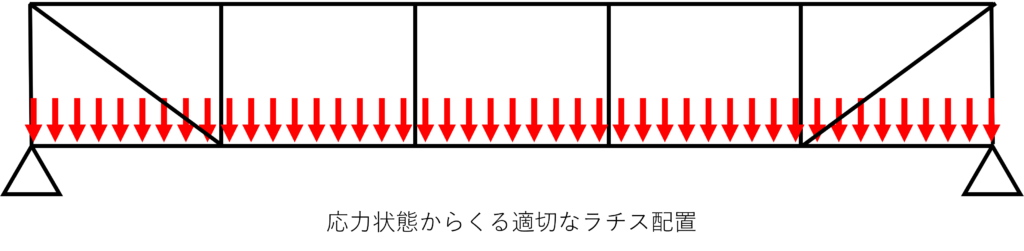
なぜこのような構成となったのかは、要求条件や意匠上の理由などが考えられますが、調べた範囲では設計を解説した資料は見つかりませんでした。
仮説の一つとしては、ミロードビル側に取り付けられた階段を利用する人にとっては、斜めのラチス材が邪魔になる可能性があるため、それを避けるために設計者がラチス材を外したのではないかと思われます。一部のラチス材だけを取り除くと意匠上の統一感が損なわれるため、端部全体のラチスを取り除いた可能性があります。
構造的な最適化だけでなく、人や車など様々な要件から生じる制約条件を考慮して構造物が設計されていることが伺え、非常に興味深いです。
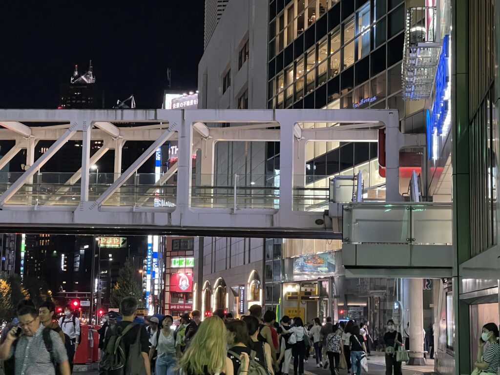
写真ー階段取り付き箇所
まとめ
今回は、構造エンジニアの視点から見た都内のユニークな橋梁を巡る旅をしてみました。
日々目にする構造物に対して、応力や変形の状態を思い描きながら、その背後に隠された設計の制約を推測すると、まったく異なる視点での観察が可能になります。
今年は例年よりも暖かい日が続いていますので、週末の散歩で近場の構造物を訪れてみるのも楽しいかもしれませんね。
文章校正:ChatGPT-4
Introduction
We have engineers with backgrounds in various engineering fields such as mechanics, fluid dynamics, physics, mathematics, architecture, and so on, with the common denominator being a love of geometry and mechanics.
Although there are common theories such as material mechanics, structural mechanics, and vibration engineering as a common language, the objects to be designed in each field differ greatly, and I enjoy learning about the thought process of structures, differences in systems, industry conventions, and technical terms every day.
Among our engineers, structural engineers with backgrounds in architecture and civil engineering were involved in the structural design of buildings and bridges, which are the largest objects that people use every day without even knowing it.
In this article, I would like to describe how structural engineers in the architectural and civil engineering fields view structures, using bridges in Tokyo as an example.
menu
In this article, I will take the following four bridges in Tokyo as examples and explain their structures.
All bridges can be reached within 30 minutes from JR Tokyo Station by train.
Incidentally, our company is located about a 25-minute walk from JR Tokyo Station.
1:Chiyoda Line Arakawa Bridge
2:Hamamatsucho Station Straddling Humanitarian Bridge
3:Bridge Shibuya 21
4:Koshu-kaido Pedestrian Bridge at South Exit of Shinjuku Station
Chiyoda Line Arakawa Bridge:Warren Truss
Year built:1968年
design:不明
structural form:Warren Truss
Span Length:No information
use:railroad bridge
This bridge is probably a familiar sight to those coming to Tokyo from the Chiba area on the JR Joban Line and Tokyo Metro Chiyoda Line.
There are four railroad bridges at this location, the JR Joban Line, Tokyo Metro Chiyoda Line, Tobu Isezaki Line, and Tsukuba Express, most of which are "Warren trusses".
There are various types of truss structures, such as Pratt trusses, Haut trusses, etc. In the case of Warren trusses, the amount of steel frame can be reduced by omitting the vertical members in the middle, which is economical and widely used.
Photo Span Details
The following conceptual diagram is a simple representation of the structure.
This is a structural form in which diagonal latticework is inserted to connect the upper and lower string members.
Since it is necessary for ships to pass under the bridge, rails are installed on the lower stringers to allow trains to pass.
The axial force and bending moment diagrams for this bridge are described below.
Basically, the upper lattice bears the compressive force and the lower lattice bears the tensile force. For the lattice members in between, there are both compressive and tensile members.
As for the bending moment, the fixed load around the track and the running load of the train are only applied to the lower string members, and almost no bending moment is generated in the upper string members and lattice members.
The bending moment diagram assumes that each member is rigidly connected, but the structural form can function without problems even if each member is pin-connected.
Hamamatsucho Station Straddling Humanitarian Bridge:Firendiel truss
Year of construction: 1984
Design: Japan National Railways
Structure: Ferendiel truss
Span length: Approx. 65 m
Use: Pedestrian bridge
Remarks: 1984 JSCE Tanaka Award
This is a humanitarian bridge on the east side of JR Hamamatsucho Station, which you may see when you use the JR Yamanote Line or the Tokyo Monorail when you go to Haneda Airport.
It is an important bridge that connects the station and the east side of the station across trains and Shinkansen lines.
The following is a conceptual structural drawing of a Ferendiel truss.
Unlike the Warren truss, the Firendiel truss is composed of only horizontal and vertical members, and has no diagonal members. Unlike the Warren truss shown in the previous section, each member must be rigidly connected to form a structure.
The axial force and bending moment diagrams are shown below.
The situation in which compressive and tensile forces act on the upper and lower members, respectively, remains the same. Instead, a large bending moment acts on the vertical members. This is because the vertical members bear the axial forces that were borne by the lattice members in the warren truss.
In general, it is more efficient for a structural member to bear axial forces than bending moments. Therefore, it is more efficient to use lattice members such as Warren trusses and Pratt trusses, etc. However, the interior of the Hamamatsucho Station Bridge is indoor. It is assumed that the Feulendahl truss was chosen because it does not obstruct the view of the trains from the windows.
It is interesting to note that structural rationality alone does not determine the structural form.
Bridge Shibuya 21: Trussed Firendiel
Year of construction: 2000
Design: Tokyu Corporation (General Design) + Architect Five (Design Design)
+ Umezawa Architectural & Structural Laboratory Inc.
Structure: Truss type firendir
Span length: 50m
Use: Pedestrian bridge
Remarks: Good Design Award 2001 (Architectural and Environmental Design Category)
This pedestrian bridge appears as soon as you exit the South South Exit of JR Shibuya Station and go west along the highway. It is located at the foot of Cerulean Tower.
Incidentally, in episode 94 of the Jutsu Kaisen, Torajo and Fushikuro confront the enemy near this pedestrian bridge and the battle begins.
This pedestrian bridge is a rarity for a bridge, as it was designed by an architect and a structural engineer. This bridge is a rare example, as architecture and civil engineering do not often cooperate with each other because their aesthetics do not match.
The bridge gives the impression of floating on the road, avoiding the ruggedness that is often associated with truss structures due to the assembly of members. The size of each member can be smaller than that of a Ferendiel truss.
Photo - Partial detail
A conceptual structural diagram is shown below.
The member arrangement is similar to that of the first Warren truss, but the lattice members are separated from each other and joined to the string members.
The axial force and bending moment diagrams are shown below.
Depending on the angle of the lattice members, the stress state is between that of a Warren truss and a Fehrendahl truss, with each member bearing the axial force and bending moment in good balance.
By adjusting the angle of the lattice members, it is possible to control the silhouette of the members by manipulating the stress state of each member.
The structure is not only aesthetically pleasing but also structurally pleasing.
Shinjuku Station South Exit Koshu-kaido Pedestrian Bridge: Plat + Firendiel Truss
Year of construction: 1998
Design: Kawada Engineering
Structure: Platt truss + Ferendiel truss
Span length: Approx. 54m
Use: Pedestrian bridge
This pedestrian bridge is located on the west side of the South Exit of JR Shinjuku Station. It connects the Odakyu Milord Building and Shinjuku Southern Terrace.
This bridge is a bit unique, and one wonders how it came to be so.
A conceptual structural drawing is shown below.
The bridge is a Fehrendiel truss at the ends and a Pratt truss in the center, and the structural type changes from the middle of the bridge.
At first glance, one might think that the structural form is appropriately divided according to the stress state, but this is not the case.
The axial force and bending moment diagrams are shown below.
Because the shear forces from equally distributed loads are greater at the bridge ends, the shear forces on the vertical members of the Fehrendahl truss are also greater at the ends.
As mentioned above, it is more efficient to use structural members as shaft members than as bending members, so if lattice members are placed appropriately in terms of stress, it is more efficient to place them at the ends because the axial forces they bear are greater.
The reason for this configuration may be due to requirements or design reasons, but as far as I could find, I could not find any documents explaining the design.
This is a hypothesis, but the pedestrian bridge in question has a staircase attached to the side of the Milord Building. The designer may have removed the diagonal latticework because he did not want people using the stairs to hit their heads against the diagonal latticework. If the latticework was removed from only one structure, the design would not be consistent, so I suspect that the latticework at the ends was removed from the entire structure.
It is very interesting to see how the structure is made not only by optimizing the structural members, but also by taking into account the restrictions imposed by various factors such as people and cars.
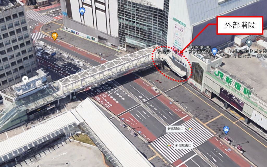
Photo - Stair-step area
conclusion
In this issue, we have toured some of the most characteristic bridges in Tokyo through the eyes of a structural engineer.
Structures that we see every day can be viewed in a completely different way if we imagine the stress and deformation conditions and the design constraints that lie behind them.
This year's weather is warmer than usual, so why not take a weekend stroll around the structures in your neighborhood?
