
トポロジー最適化や陰関数モデリングなどの形状生成手法では、結果がMeshとして出力されることがあります。また、3Dスキャンなどの形状計測でも、取得した形状は点群やMeshとして扱われるのが一般的です。
これらの形状を既存のCADワークフローで編集したり、設計データとして再利用したりするためには、Brepへの変換が求められる場合があります。
ただし、MeshをBrepに変換するといっても、元のMeshに忠実な形状が欲しいのか、編集しやすいCAD形状が欲しいのかによって、適した方法は変わります。
本記事では、MeshをBrepに変換する代表的な方法を整理し、いくつかの方法を実際に試した結果を紹介します。
Brep化の目的と求められる形状
Brep(Boundary Representation)は、面・稜線・頂点によって立体の境界を表現する形状表現です。一般的な3D CADでは、平面やNURBS曲面などを組み合わせたBrepが、設計形状の表現に広く使われています。
一方、Meshは三角形や四角形の集合によって形状を表す、形状の可視化や3Dプリントなどに利用しやすい形状表現です。
CAD上の操作や後工程では、Brepの方が扱いやすい場合があります。たとえば、以下のような作業ではBrepの方が便利です。
- フィレットや面取りなどのCAD編集
- 寸法変更
- 図面化
- 解析用メッシュを生成するためのCADモデルの作成
- 他CADシステムとのデータ連携
ただし、単にBrepに変換できればよいわけではありません。変換後の用途によって、求められる形状は異なります。
寸法変更や穴径の変更など形状の特徴に基づく編集を想定する場合は、平面や円筒面などの形状の特徴に沿って整理されたBrepが扱いやすくなります。一方、意匠面や有機的な形状では、元のMeshとの一致度や曲面の滑らかさが重要になります。
数値解析に利用する場合は、Brepを解析用メッシュの生成元となる形状として使用します。そのため、元形状の再現性だけでなく、微小な隙間や重複面がなく、解析用メッシュを安定して生成できることも重要です。
このように、MeshからBrepへの変換は単なるファイル形式の変換ではなく、用途に合わせて形状を再構成する処理として考える必要があります。
MeshからBrepを作る代表的なアプローチ
MeshからBrepを作る方法には、Meshの面をそのままBrep化する方法から、元の形状を参照しながらCAD形状として作り直す方法まで、さまざまなものがあります。
方法によって、得られるBrepの面構成や、元のMeshとの関係、変換後の編集方法が異なります。
以下では、代表的な6つのアプローチについて、それぞれの考え方と実例を紹介します。
1. プリミティブなBrepに変換する
Meshから平面、円筒、球、円錐などの単純な形状を検出し、それらを組み合わせてBrepを作る方法です。
この方法のメリットは、BrepがシンプルでCAD上で編集しやすいことです。一方で、自由曲面や複雑な形状を少数のプリミティブな形状だけで表現するのは難しいです。
機械部品のように、平面や円筒面が多い形状に適した方法です。
実例
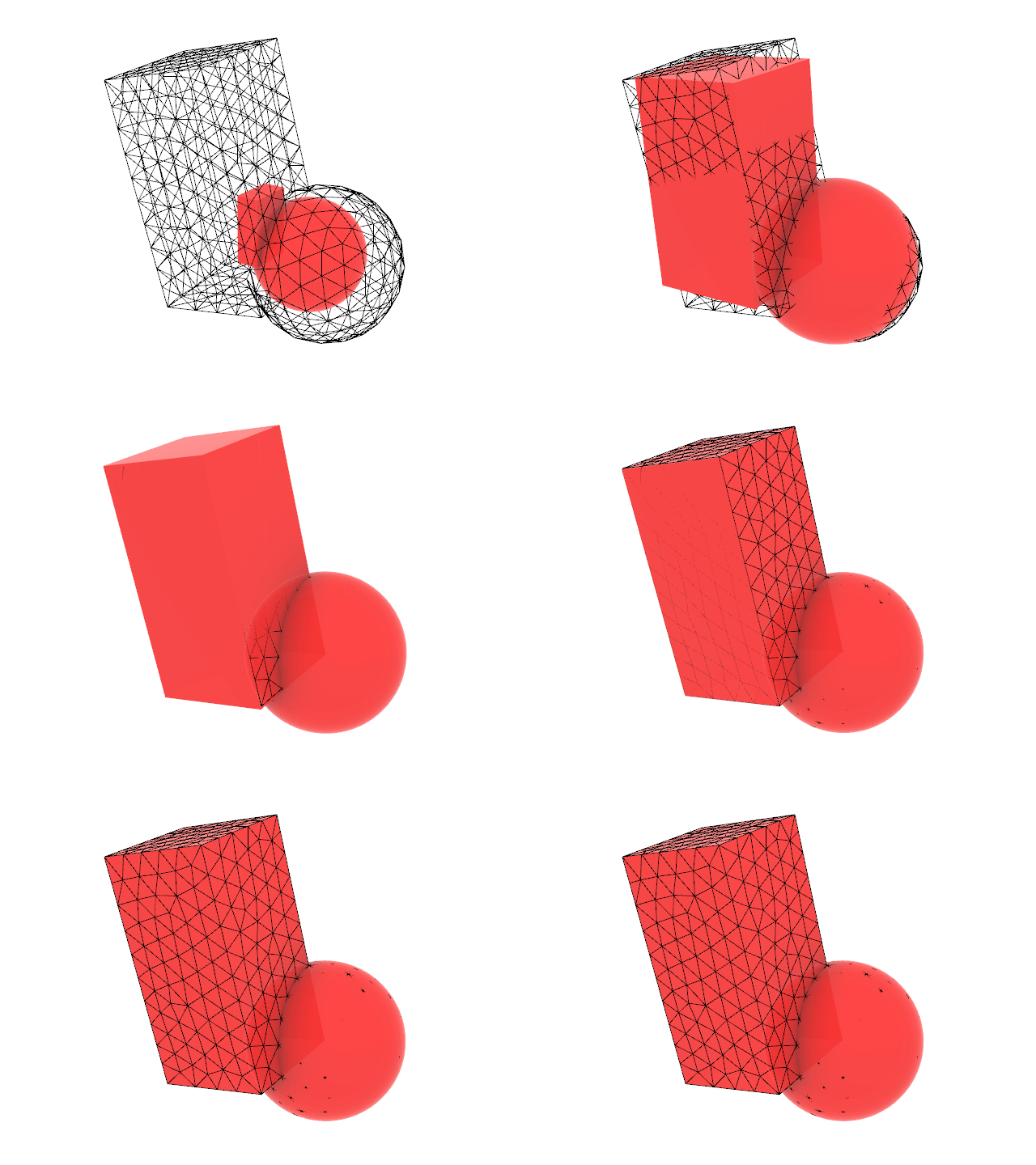
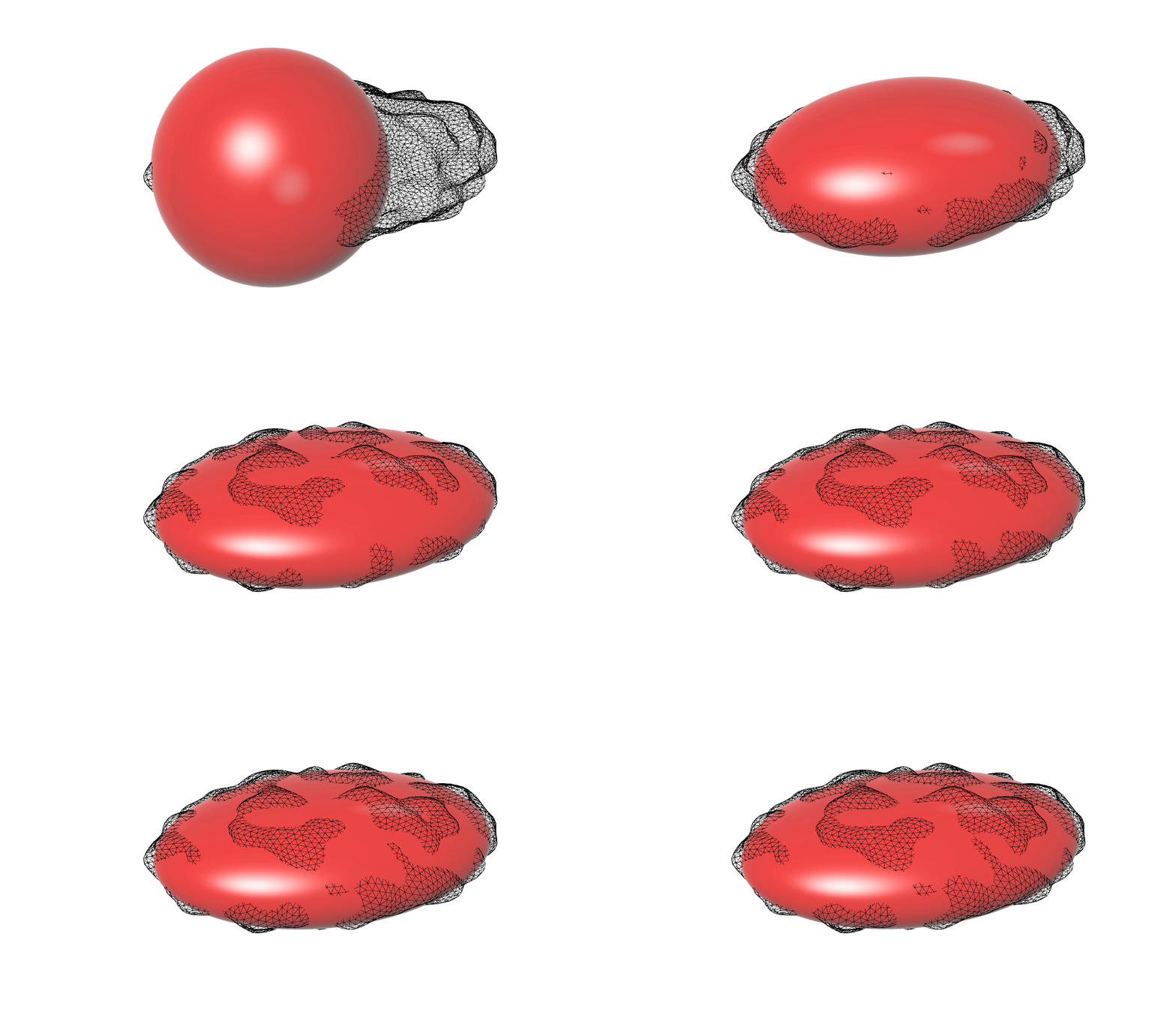
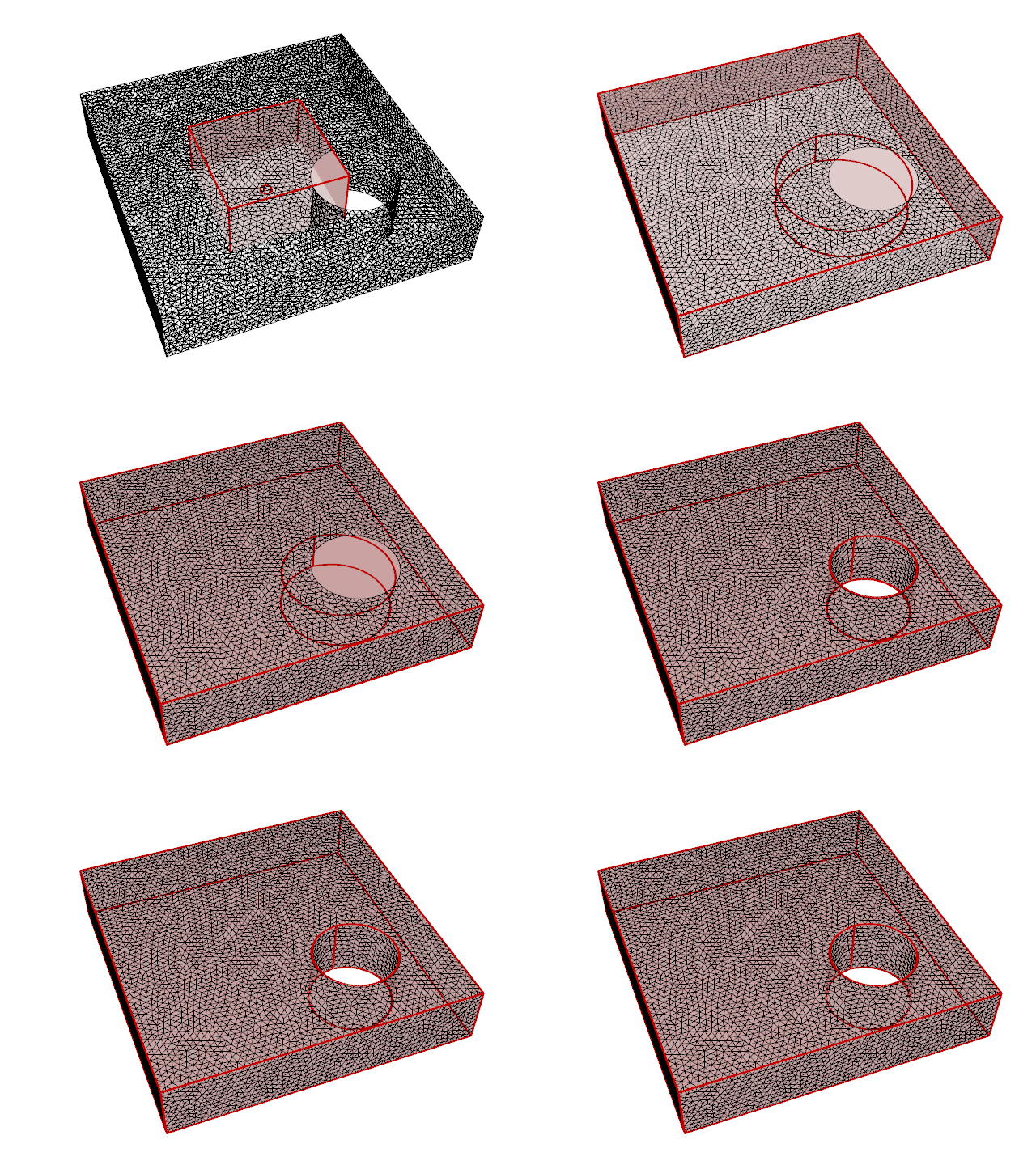
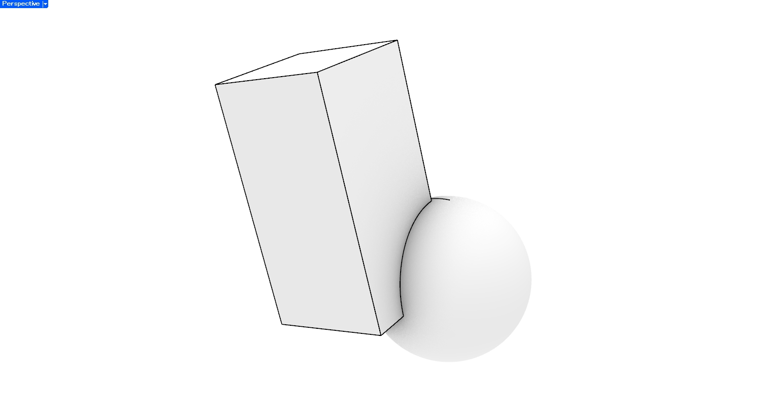
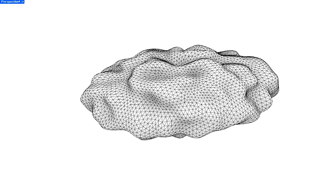
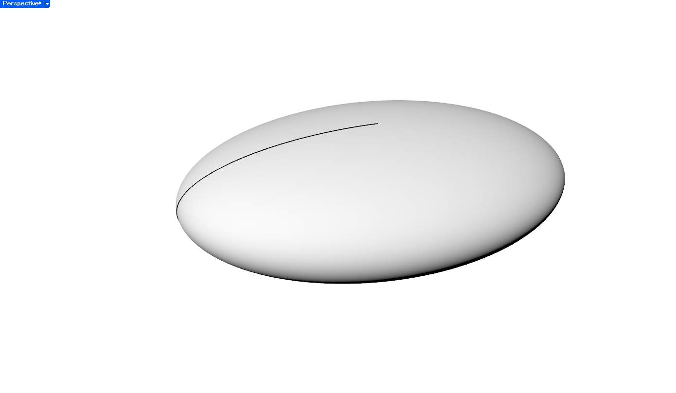
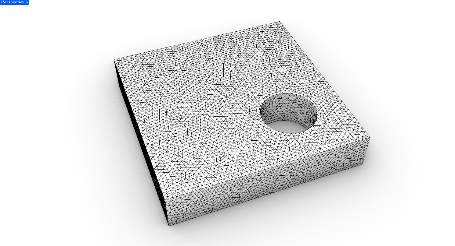
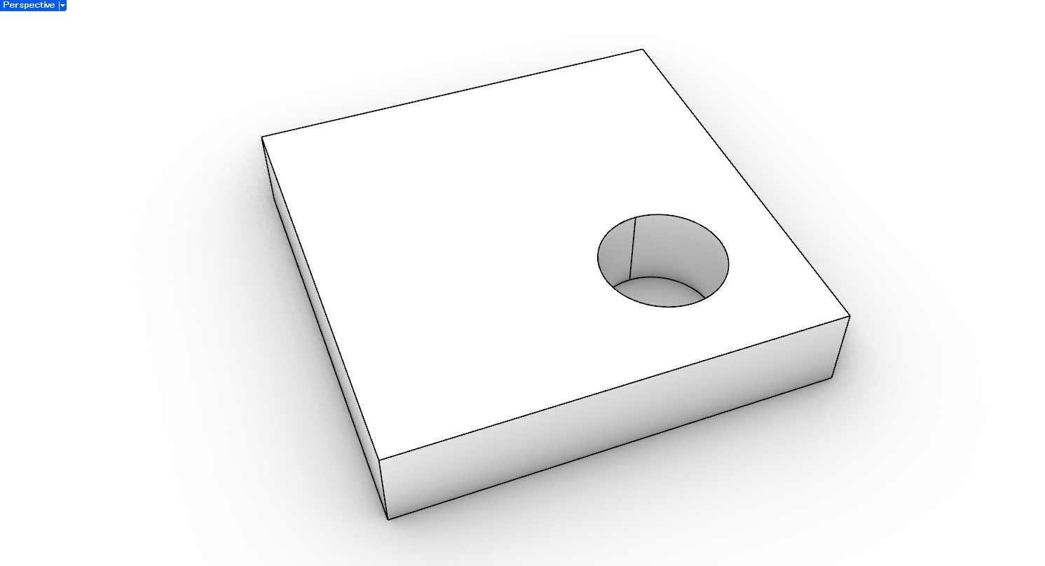
一般的には、Meshから平面や円筒面などの領域を抽出し、それらをプリミティブなCAD面として再構成する方法がよく使われます。今回は、フィッティングの様子を分かりやすく示すために、Brep形状のパラメータを変化させ、Mesh上サンプリング点とBrepの二乗距離の和を最小化するフィッティング方法を用いました。
Mesh
Brep
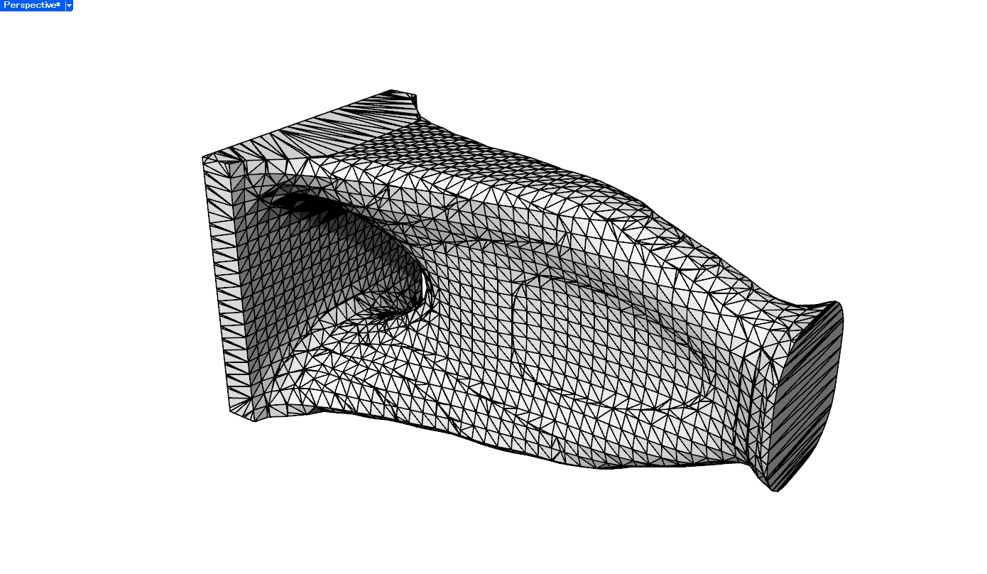
2. Meshの各面をそのままNURBSパッチ化する
Meshの各面を、対応するNURBS面またはトリムされたNURBS面としてBrep化する方法です。
実装は比較的シンプルで、元のMesh形状との一致度も高くなります。
一方で、Meshの面数が多いほどBrepの面数も増えるため、データが非常に重くなります。また、面構成は元のMeshとほぼ同じであるため、CAD上で編集しやすい形状になるとは限りません。
形状をほぼ維持したままBrep形式に変換したい場合には有効ですが、設計編集用のモデルとしては注意が必要です。
実例
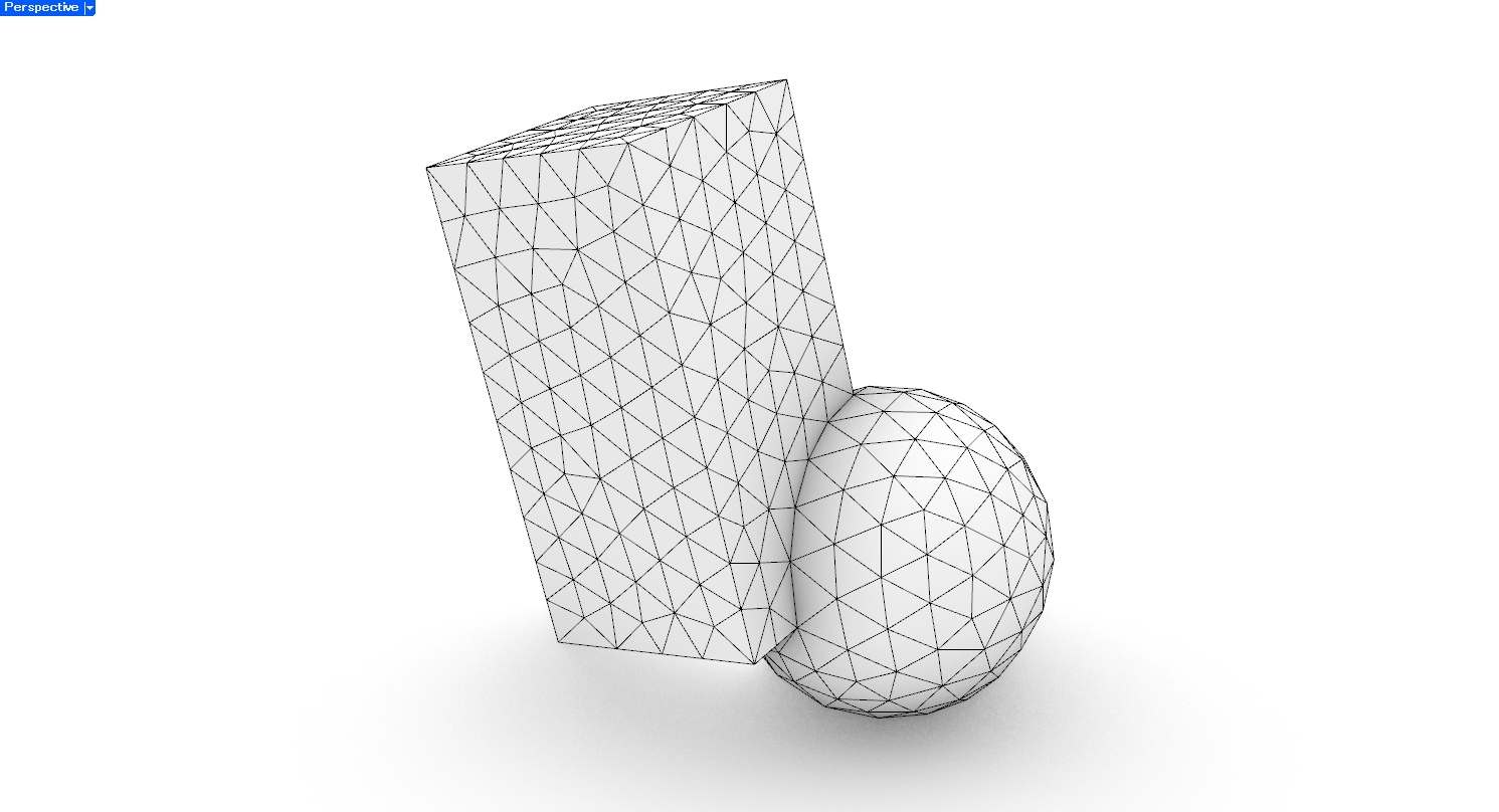
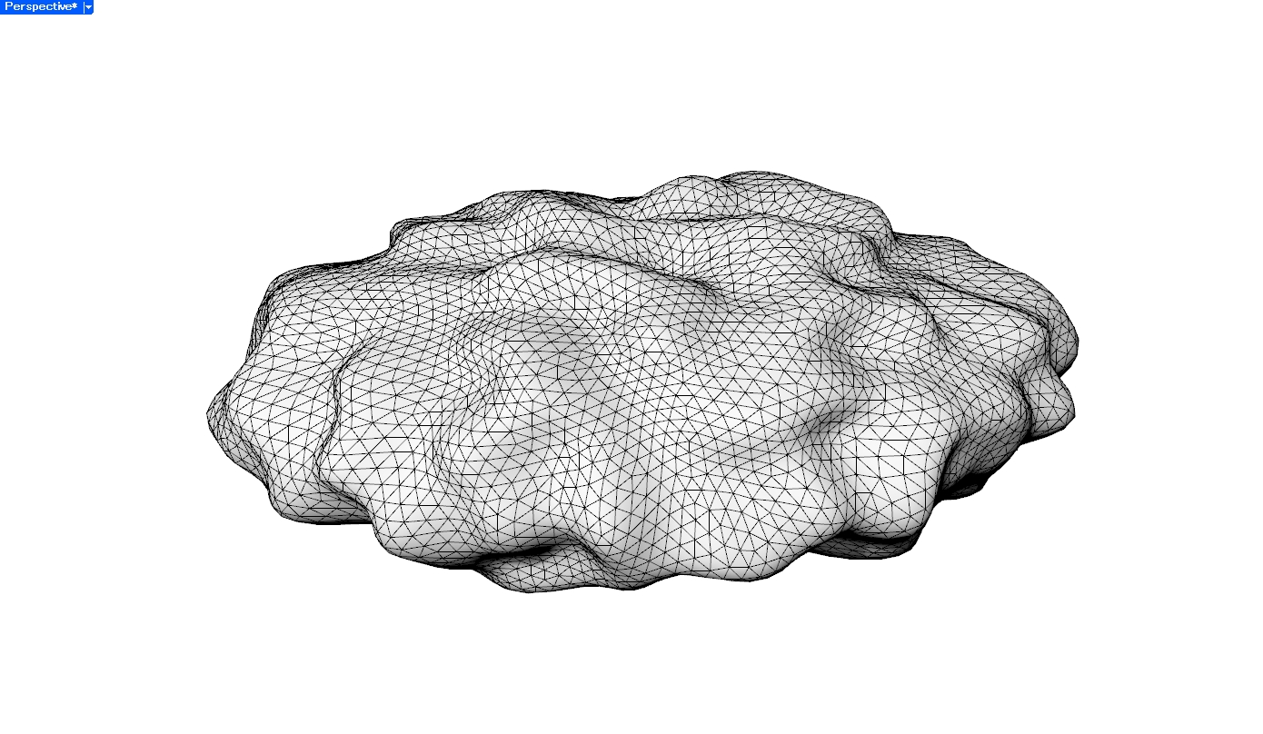
Mesh
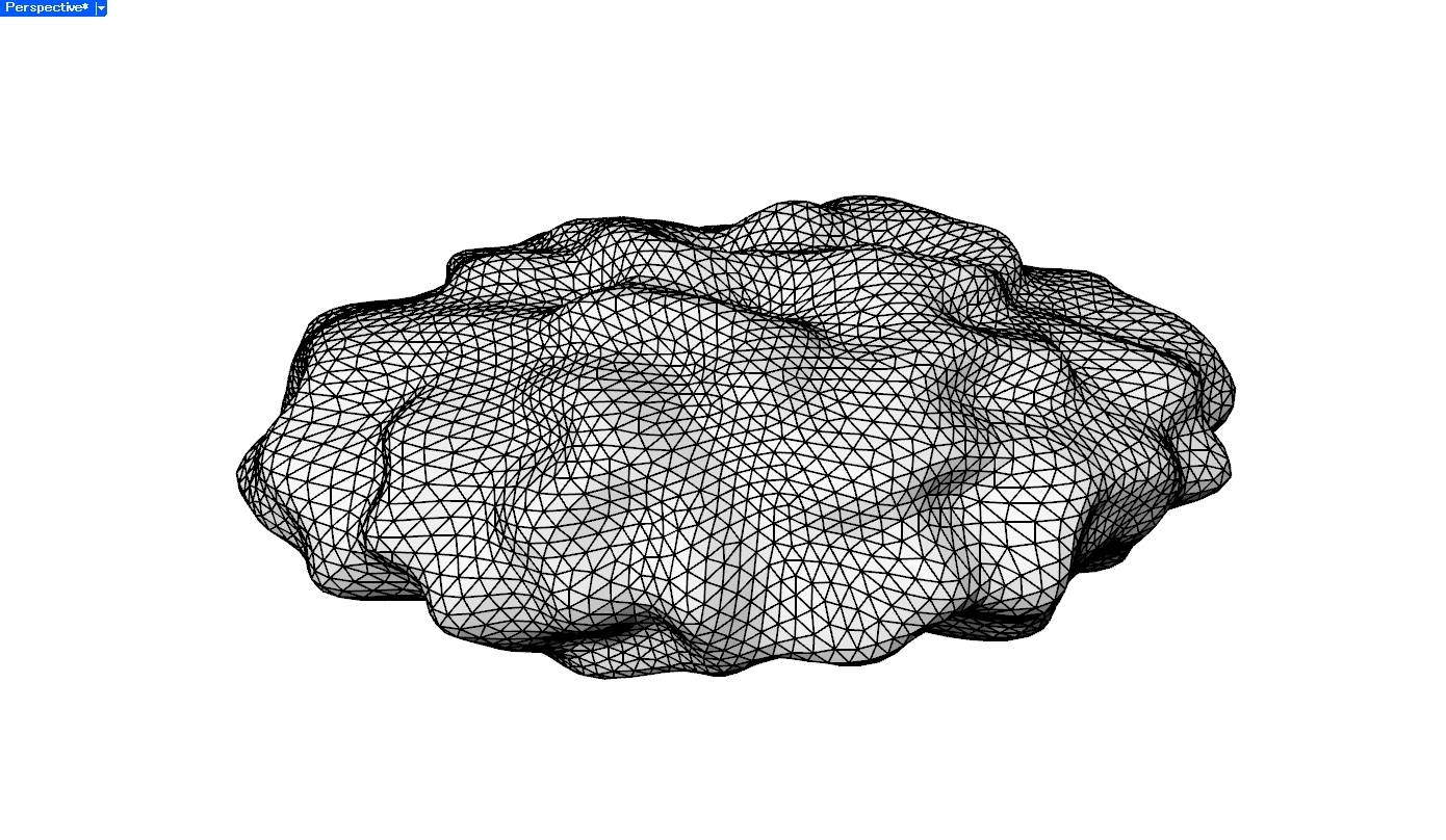
Brep
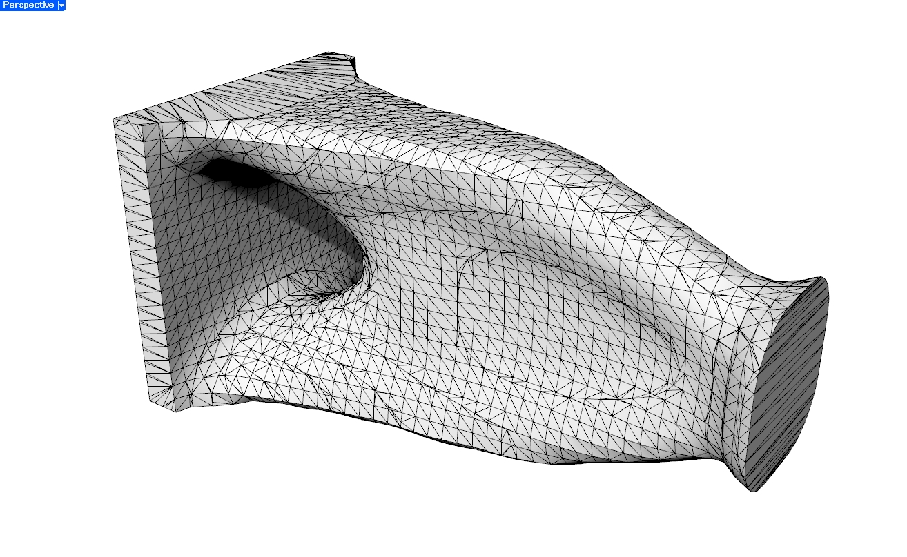
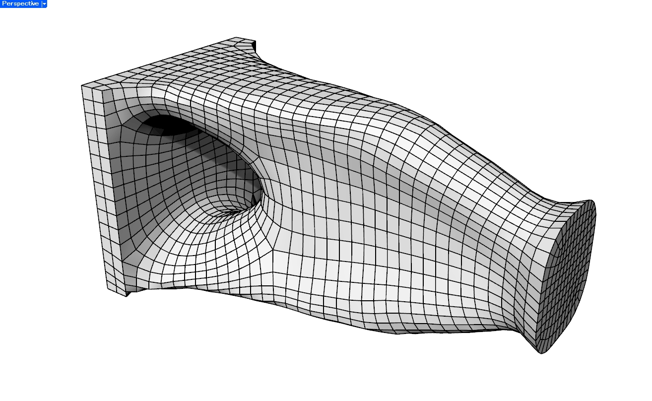
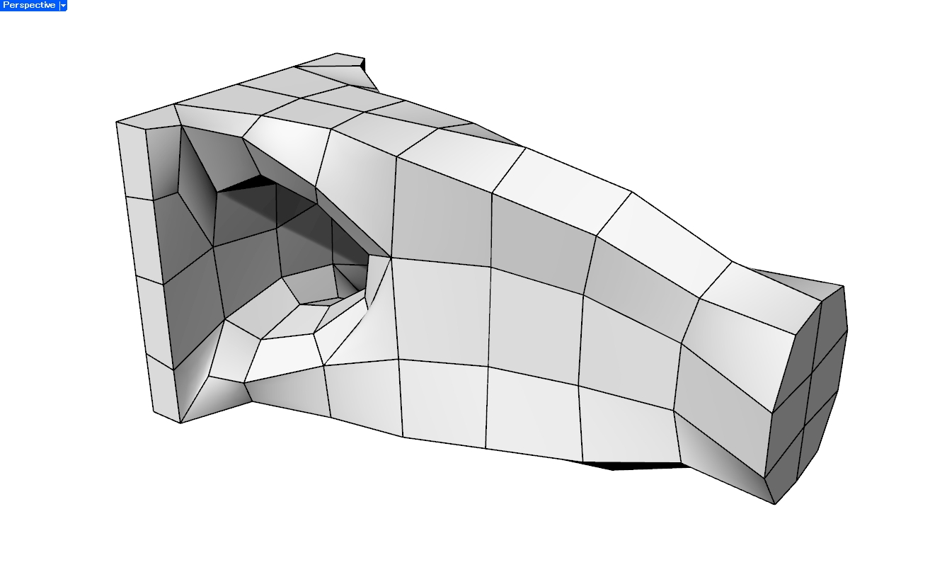
3. リメッシュしてからBrep化する
元のMeshを一度Quad Meshなどにリメッシュし、その面構成に沿ってBrep化する方法です。
Meshの各面をそのままBrep化する方法と比べて面数を減らしやすく、曲面の流れも整理できます。ただし、得られるBrepの面構成はリメッシュ結果に大きく依存します。
実例
Mesh
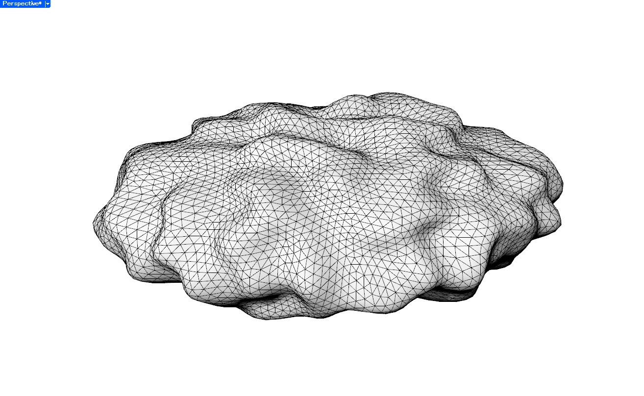
細かくリメッシュ
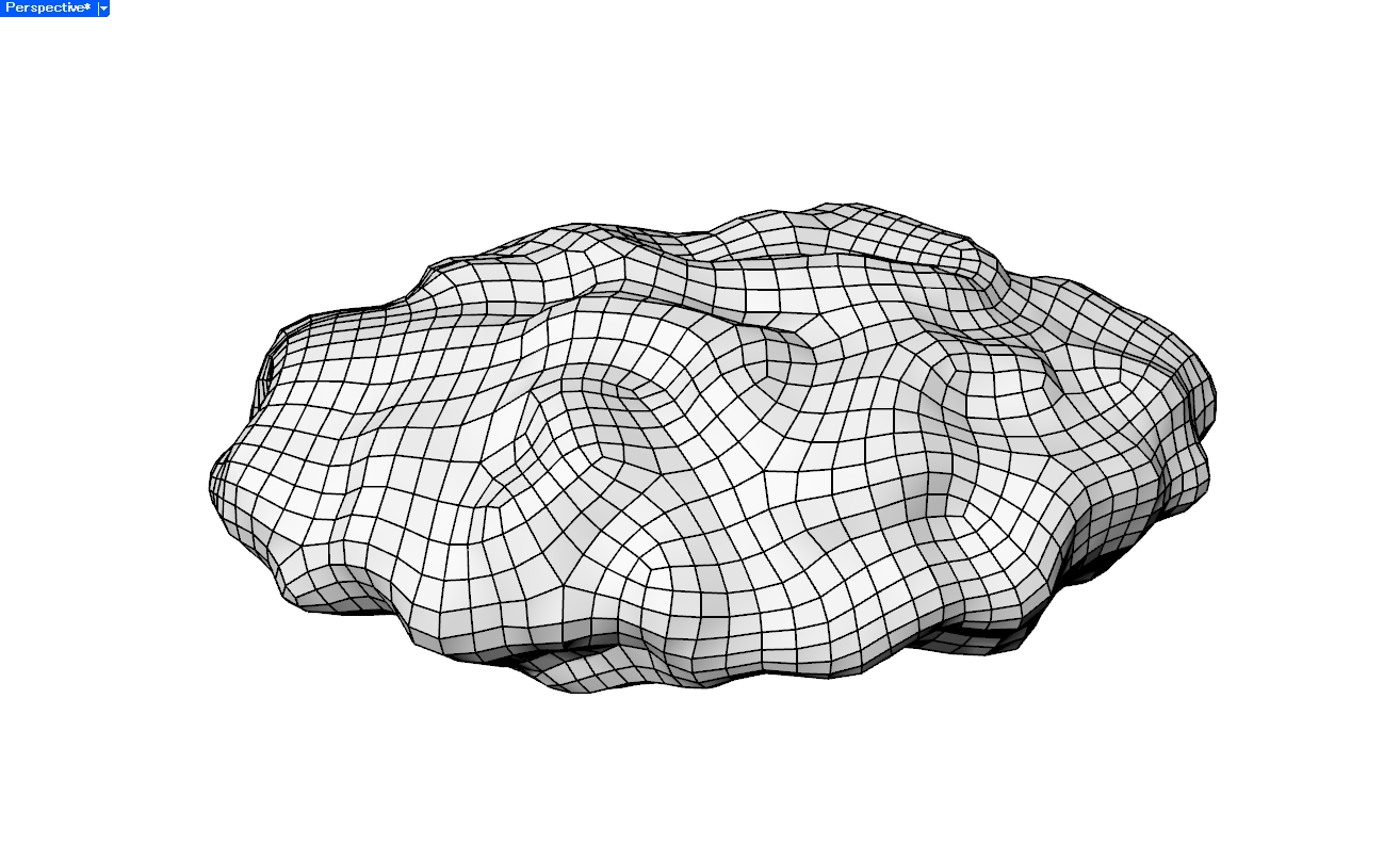
粗くリメッシュ
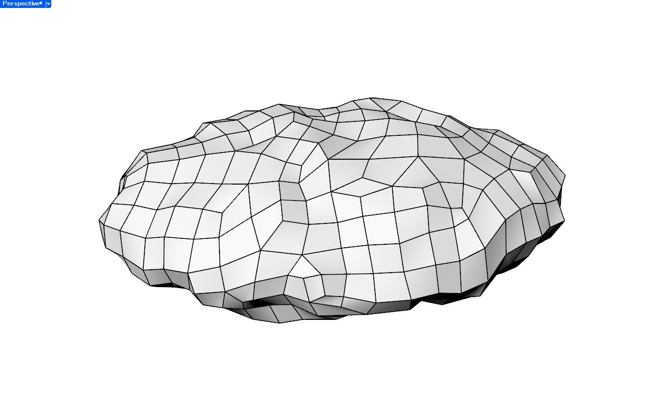
4. MeshにNURBS曲面をフィットする
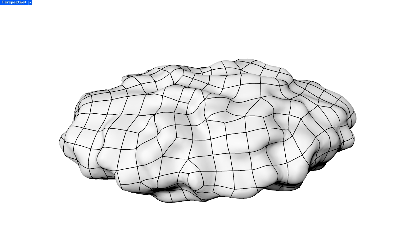
Meshの頂点や面を参照して、滑らかなNURBS曲面を近似的に当てはめる方法です。
適切にMeshをリメッシュしてフィットできれば、元のMeshよりも滑らかで少ない面数のBrepとして表現できる場合があります。
一方で、曲面をどのように分割するか、制御点数をどの程度にするか、どこまで近似誤差を許容するかといった設定が必要です。
自由曲面や意匠面のように、滑らかさを重視したい場合に向いています。
実例
Mesh
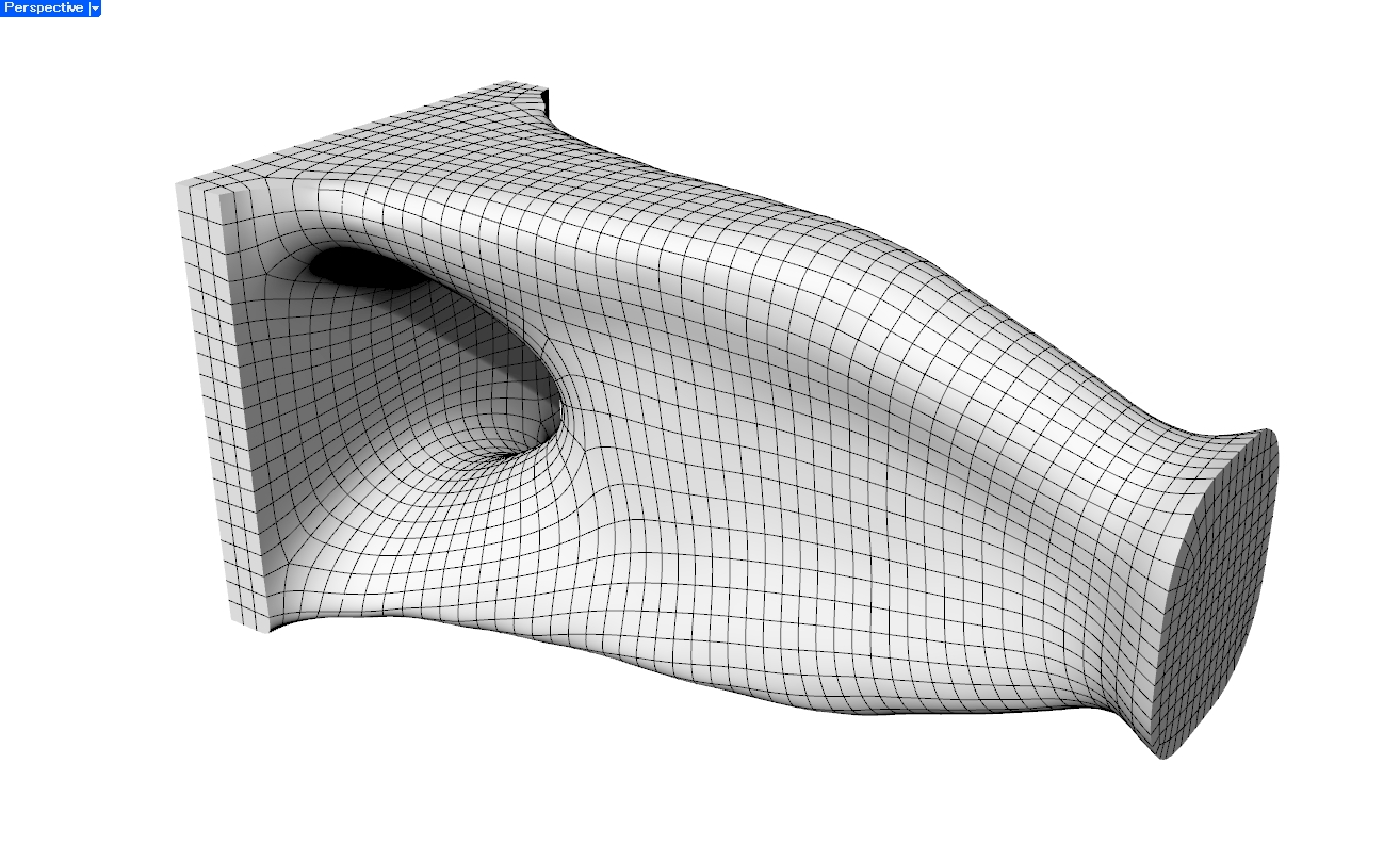
リメッシュ後Brep
フィッティング後Brep
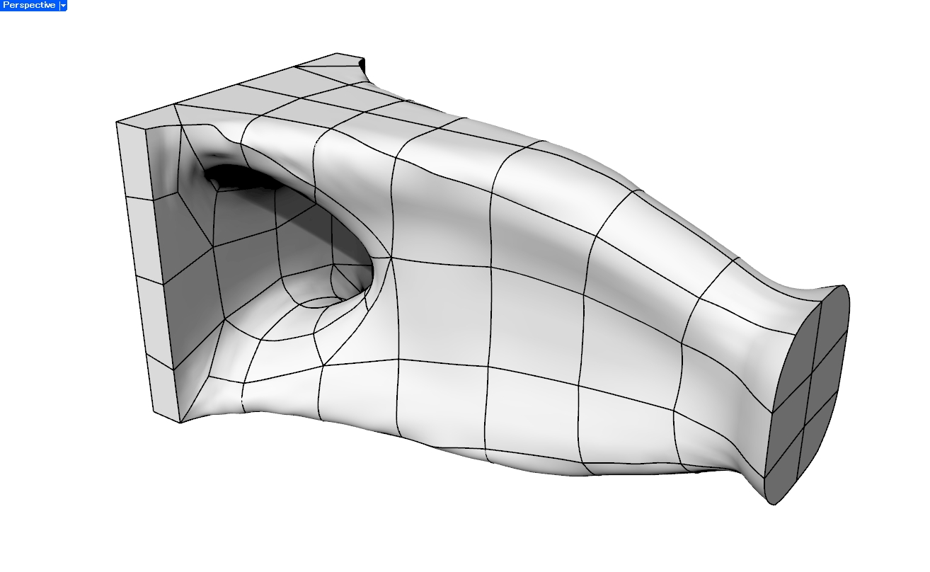
5. SubD経由でBrepに変換する
Meshを一度SubDに変換し、その後Brepに変換する方法です。
SubDは、ポリゴン形状をもとに滑らかな曲面を作る表現です。比較的少ない制御点で滑らかな形状を表現できるため、Meshの細かな面構成をそのまま引き継がず、整理された曲面としてBrepに変換しやすいという特徴があります。RhinocerosなどのCADソフトでは、MeshからSubD、SubDからBrepへの変換機能が用意されています。
この方法は、有機的で滑らかな形状に向いています。一方で、元のMeshを近似する形状となるため、鋭いエッジや平面を保ちたい場合には注意が必要です。
実例
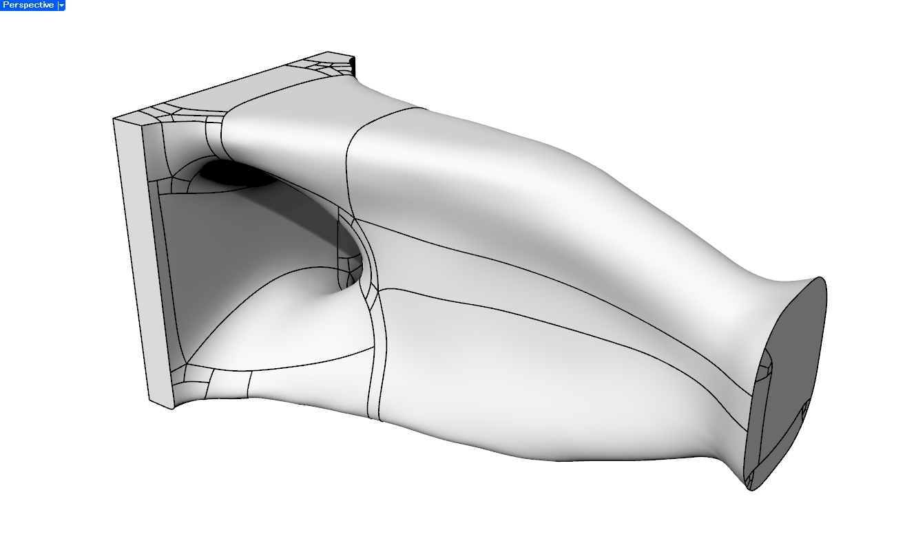
RhinocerosのToSubDおよびToNurbsコマンドにより変換しています。
Mesh
リメッシュ⇒SubD
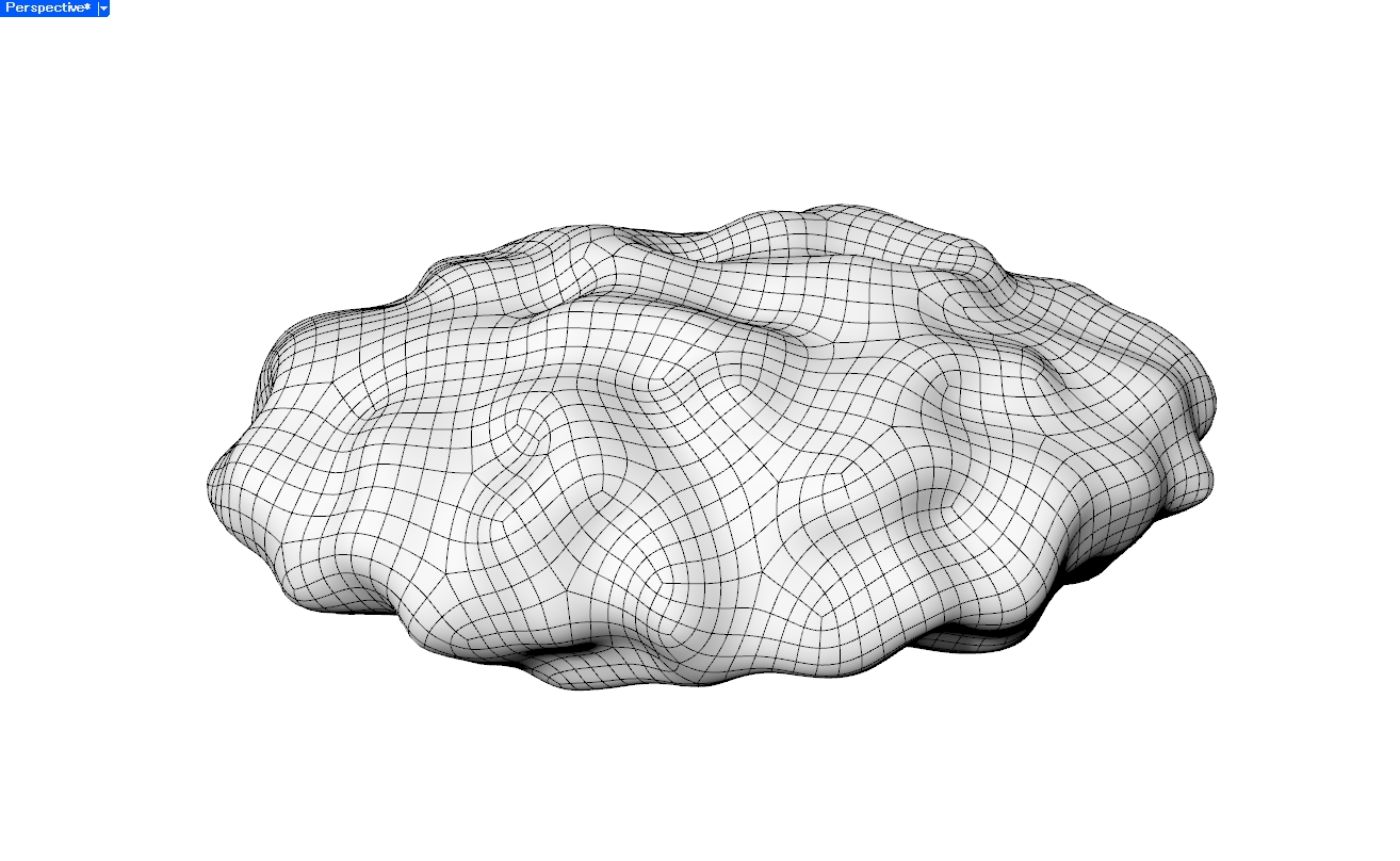
Brep
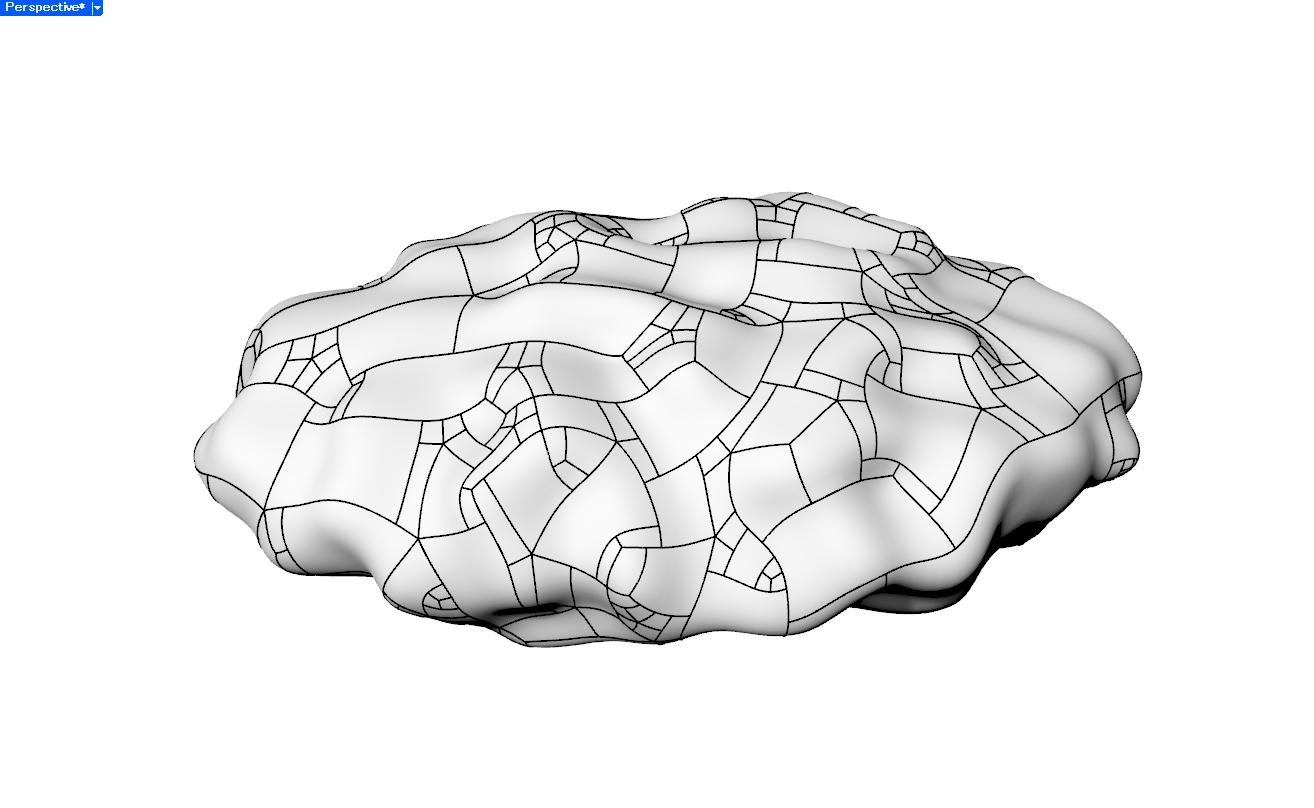
6. 断面カーブから再構成する
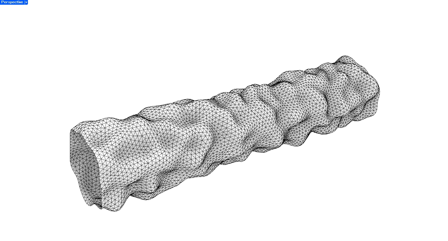
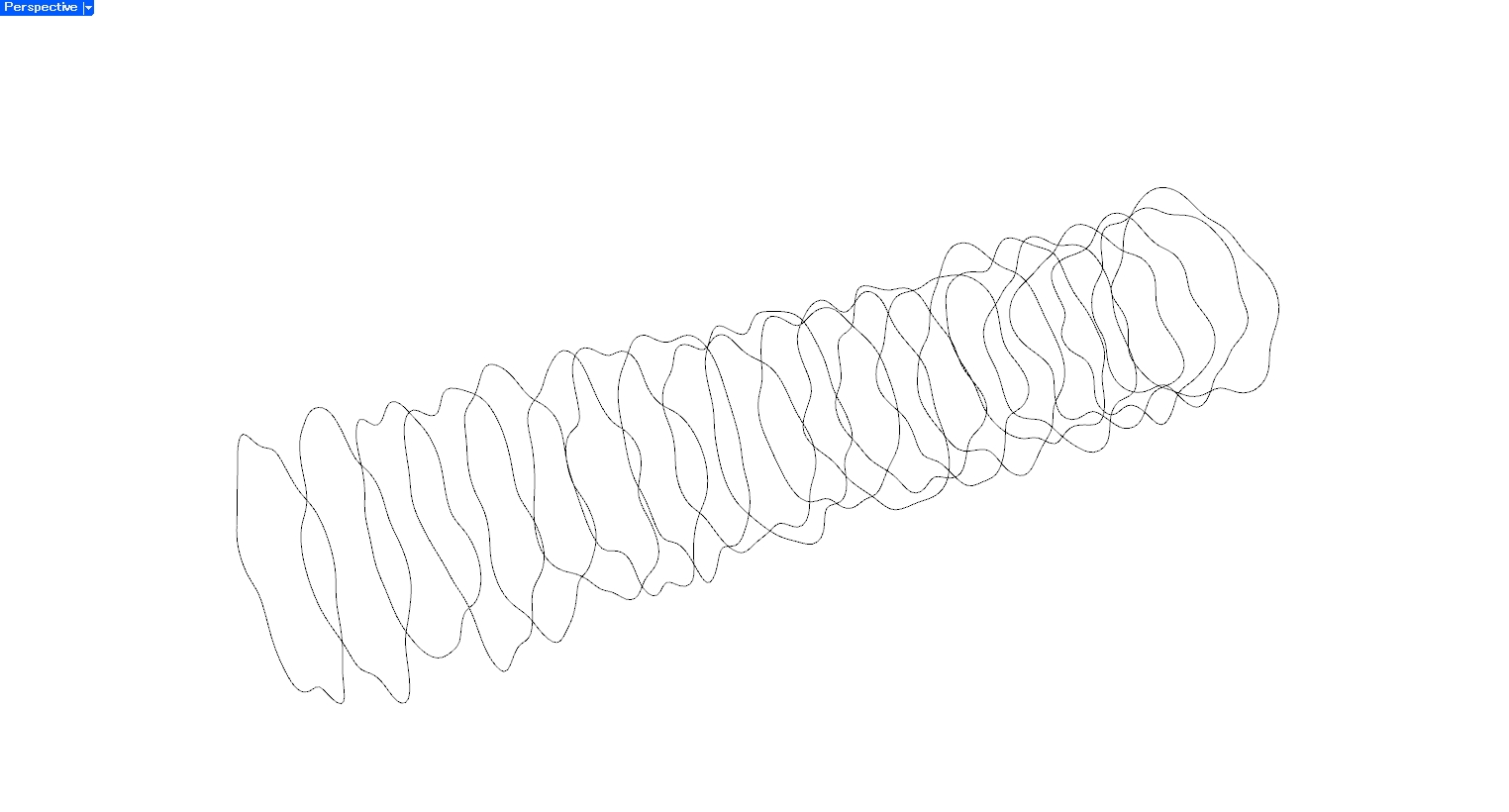
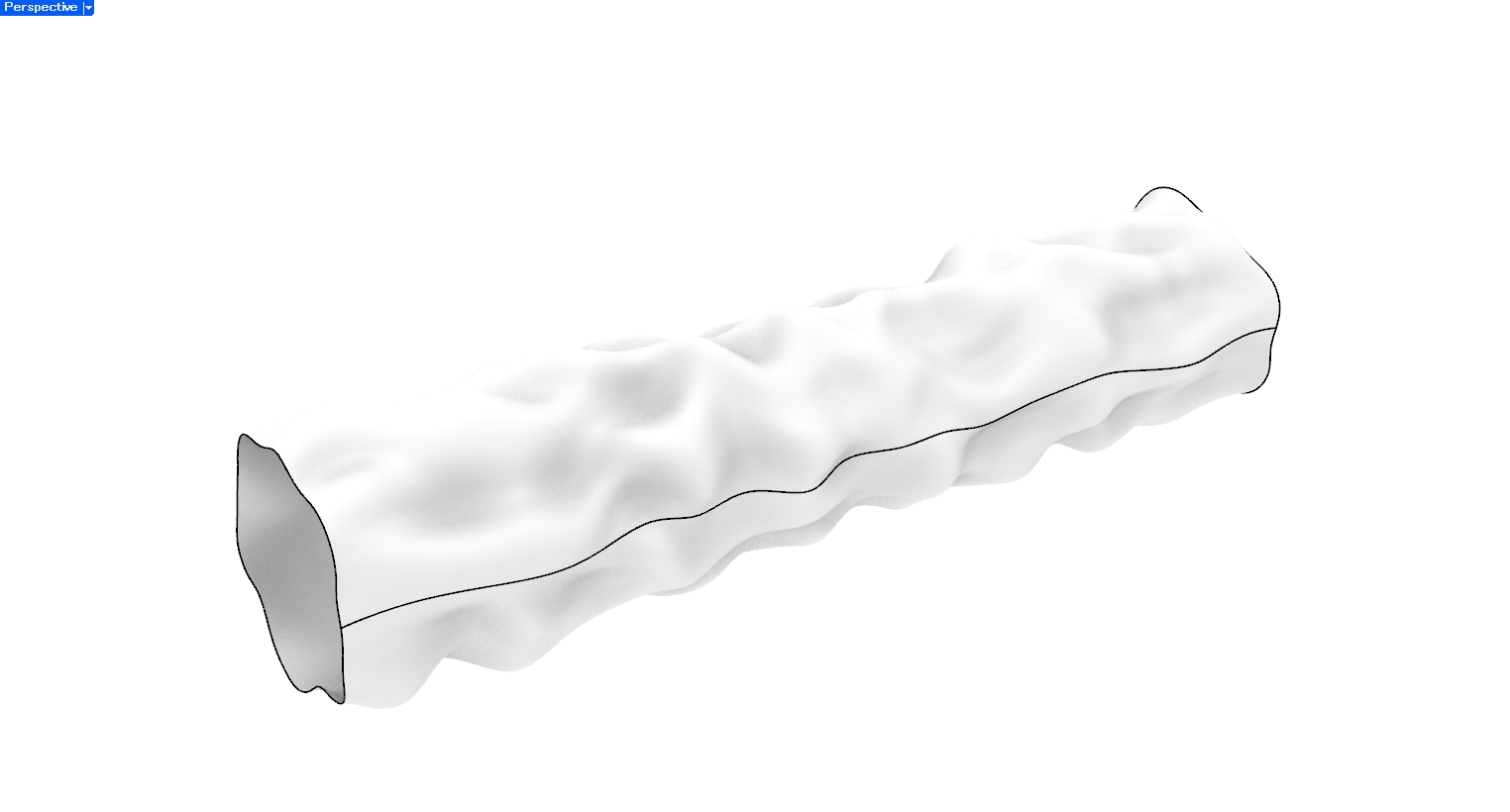
Meshから断面カーブや特徴線を抽出し、ロフト、スイープ、押し出しなどのCAD操作でBrepを作り直す方法です。
Meshを直接変換するというより、Meshを参照しながらCADモデルを再構成する方法です。
配管形状、押し出し形状、回転体のように、形状の作り方がある程度想定できる場合に向いています。得られるBrepは編集しやすい一方で、形状ごとの処理が必要になります。
実例
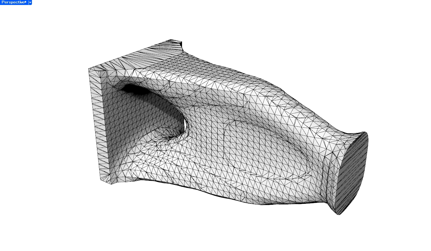
Mesh
特徴線
Brep
各アプローチの特徴
ここまで紹介したように、MeshからBrepを作る方法には、それぞれ得意な形状や仕上がりの違いがあります。
今回の実例は厳密な性能比較ではありませんが、方法を選ぶ際の目安として、各アプローチの特徴と注意点を整理します。
| アプローチ | 選択の目安 | 特徴・注意点 |
|---|---|---|
| 1. プリミティブなBrepに変換する | 平面・円筒面・球面などで表せる形状を、寸法変更しやすい形にしたい場合 | シンプルなBrepを得やすい、自由曲面の再現には向かない |
| 2. Meshの各面をそのままNURBSパッチ化する | 元のMesh形状をできるだけ維持したままBrep化したい場合 | Meshとの一致度が高い、面数が多くデータが重くなりやすい |
| 3. リメッシュしてからBrep化する | 面数や面の流れを整理してBrep化したい、または後工程のために面構成を整えたい場合 | 面数を減らせる、リメッシュにより形状が変化する場合がある |
| 4. MeshにNURBS曲面をフィットする | 近似精度や曲面構成を調整しながら、自由曲面を滑らかなBrepとして近似したい場合 | 滑らかに形状を近似できる、曲面の分割方法や制御点数の適切な設定が必要となる |
| 5. SubD経由でBrepに変換する | SubDの面構成を利用して、形状全体を滑らかな曲面として再構成し、Brep化したい場合 | 滑らかに形状を近似できる、鋭いエッジや平面の保持には適切な設定が必要となる |
| 6. 断面カーブから再構成する | 配管・押し出し形状・回転体など、断面や生成方法を想定できる形状を再構成したい場合 | 編集しやすいCAD形状として再構成できる、 形状ごとに再構成方法を考える必要がある |
MeshをBrepにするうえでの注意点
実際にMeshをBrepに変換する際には、変換前のMesh品質が重要です。
元のMeshに穴、自己交差、法線の反転、非多様体エッジなどがあると、Brep化がうまくいかないことがあります。
そのため、Brep化の前に以下のような修正が必要になる場合があります。
- 穴埋め
- 重複頂点の削除
- 法線方向の統一
- 非多様体エッジの修正
- 極端に細長い三角形の修正・除去
- ノイズの平滑化
また、Brepに変換できたとしても、それがCAD上で使いやすいとは限りません。
特に、Meshの各面をそのままBrep化した場合、見た目はBrepでも、実態は大量の小さな平面パッチの集合です。このようなデータは、CAD上での編集や後工程には向かない場合があります。
「Brep形式であること」と「CADモデルとして扱いやすいこと」は、分けて考える必要があります。
まとめ
MeshからBrepへの変換では、元形状への忠実さ、曲面の滑らかさ、面構成の単純さ、編集しやすさの間にトレードオフがあります。
元のMeshをできるだけそのまま保持したい場合は各面のBrep化、滑らかな曲面として近似したい場合はNURBS曲面フィッティングやSubD、編集しやすいCAD形状を作りたい場合はプリミティブや断面カーブからの再構成が候補になります。
重要なのは、変換そのものを目的にするのではなく、Brep化した後にどのような操作を行いたいかから方法を選ぶことです。
Shape-generation methods such as topology optimization and implicit modeling often produce their results as meshes. Similarly, shapes acquired through measurement techniques such as 3D scanning are commonly handled as point clouds or meshes.
To edit these shapes within an existing CAD workflow or reuse them as design data, it may be necessary to convert them into a Brep.
However, there is no single best way to convert a mesh into a Brep. The appropriate method depends on whether the goal is to reproduce the original mesh as accurately as possible or to obtain an editable CAD model.
This article provides an overview of common approaches for converting meshes into Breps and presents the results of applying several of these methods in practice.
Why Convert a Mesh into a Brep?
A Brep, or Boundary Representation, represents the boundary of a solid using faces, edges, and vertices. In general-purpose 3D CAD systems, Breps composed of planar surfaces, NURBS surfaces, and other surface types are widely used to represent design geometry.
A mesh, on the other hand, represents a shape as a collection of triangular or quadrilateral elements. Meshes are well suited to applications such as visualization and 3D printing.
For CAD operations and downstream processes, however, a Brep is often easier to work with. For example, Breps are generally more suitable for:
Simply converting a shape into a Brep is not always sufficient. The characteristics required of the converted geometry depend on how it will be used.
When feature-based editing is required, such as changing dimensions or modifying hole diameters, a Brep organized around geometric features such as planes and cylinders is easier to work with. For styling surfaces and organic shapes, however, fidelity to the original mesh and surface smoothness may be more important.
When the geometry is used for numerical analysis, the Brep serves as the source geometry for generating an analysis mesh. In this case, it is important not only to reproduce the original shape accurately, but also to avoid small gaps, overlapping faces, and other defects that may prevent stable mesh generation.
Converting a mesh into a Brep should therefore be regarded not merely as a file-format conversion, but as a process of reconstructing the geometry according to its intended use.
Common Approaches for Creating a Brep from a Mesh
There are many ways to create a Brep from a mesh. These range from directly converting individual mesh faces into Brep faces to reconstructing the geometry as a new CAD model while using the original mesh as a reference.
Each method produces a different face structure, preserves a different relationship with the original mesh, and offers different levels of editability after conversion.
The following sections introduce six representative approaches, together with their basic concepts and practical examples.
1. Converting the Mesh into Primitive Brep Geometry
This approach detects simple geometric shapes such as planes, cylinders, spheres, and cones within the mesh and reconstructs the geometry as a combination of these primitives.
The main advantage is that the resulting Brep is simple and easy to edit in CAD. However, it is difficult to represent freeform or highly complex geometry using only a small number of primitive surfaces.
This method is particularly suitable for mechanical components that contain many planar and cylindrical surfaces.
Example
A common approach is to identify planar, cylindrical, and other geometric regions within the mesh and reconstruct them as primitive CAD surfaces.
In this example, to clearly visualize the fitting process, the parameters of the Brep geometry were varied to minimize the sum of squared distances between sampled points on the mesh and the Brep.
Mesh
Brep
2. Converting Each Mesh Face into a NURBS Patch/h3>
This method converts each mesh face into a corresponding NURBS surface or trimmed NURBS surface within a Brep.
The implementation is relatively straightforward, and the resulting Brep closely matches the original mesh geometry.
However, as the number of mesh faces increases, the number of Brep faces also increases, which can make the data extremely large and computationally expensive. Because the face structure remains almost identical to that of the original mesh, the resulting geometry is not necessarily easy to edit in CAD.
This approach is useful when the primary objective is to preserve the original geometry while converting it into the Brep format. However, care is required when the model is intended for design editing.
Example
Mesh
Brep
3. Remeshing before Converting to a Brep
In this approach, the original mesh is first remeshed, for example as a quad mesh, and then converted into a Brep based on the new face structure.
Compared with directly converting every face of the original mesh, this approach makes it easier to reduce the number of faces and organize the surface flow. However, the face structure of the resulting Brep depends strongly on the remeshing result.
Example
Mesh
Fine remeshing
Coarse remeshing
4. Fitting NURBS Surfaces to the Mesh
This method uses the vertices or faces of the mesh as reference data and fits smooth NURBS surfaces to them.
When the mesh is appropriately remeshed and fitted, the geometry can sometimes be represented as a smoother Brep with fewer faces than the original mesh.
However, several parameters must be determined, including how the surface should be divided, how many control points should be used, and how much approximation error is acceptable.
This approach is suitable for freeform and styling surfaces where smoothness is a primary concern.
Example
Mesh
Brep after remeshing
Brep after fitting
5. Converting through SubD
This method first converts the mesh into a SubD model and then converts the SubD geometry into a Brep.
SubD is a representation that generates smooth surfaces from polygonal control geometry. Because it can describe smooth shapes using relatively few control points, it is useful for reconstructing a mesh as an organized surface model without directly preserving every small mesh face.
CAD software such as Rhinoceros provides functions for converting a mesh into SubD geometry and then converting the SubD model into a Brep.
This approach is suitable for smooth, organic shapes. However, because the resulting geometry is an approximation of the original mesh, care is required when sharp edges or planar surfaces must be preserved.
Example
The geometry was converted using the ToSubD and ToNURBS commands in Rhinoceros.
Mesh
Remeshing → SubD
Brep
6. Reconstructing the Geometry from Section Curves
This approach extracts section curves or feature lines from the mesh and reconstructs the Brep using CAD operations such as lofting, sweeping, and extrusion.
Rather than directly converting the mesh, this method uses the mesh as a reference for rebuilding the CAD model.
It is suitable for geometries whose construction method can be inferred, such as pipes, extruded shapes, and solids of revolution. The resulting Brep is generally easy to edit, but a reconstruction strategy must be developed for each type of geometry.
Example
Mesh
Feature lines
Brep
Characteristics of Each Approach
As discussed above, each method for creating a Brep from a mesh is suited to different types of geometry and produces different results.
The examples presented in this article are not intended as a rigorous performance comparison. However, the following table summarizes the main characteristics and considerations of each approach as a practical guide for selecting a method.
| Approach | When to Consider It | Characteristics and Considerations |
|---|---|---|
| 1. Convert to primitive Brep geometry | When the shape can be represented using planes, cylinders, spheres, and other primitives, and dimensional editability is required | Produces a relatively simple Brep; not suitable for accurately reproducing freeform surfaces |
| 2. Convert each mesh face into a NURBS patch | When the original mesh geometry should be preserved as closely as possible | High geometric fidelity; the large number of faces can make the model heavy and difficult to edit |
| 3. Remesh before converting to a Brep | When the number and flow of faces should be reorganized before conversion or downstream processing | Can reduce the number of faces; remeshing may alter the original geometry |
| 4. Fit NURBS surfaces to the mesh | When a freeform shape should be approximated as a smooth Brep while controlling approximation accuracy and surface structure | Can produce a smooth approximation; requires appropriate surface segmentation and control-point settings |
| 5. Convert through SubD | When the overall shape should be reconstructed as a smooth surface using a SubD-based face structure/td> | Can produce a smooth approximation; preserving sharp edges and planar regions requires appropriate settings |
| 6. Reconstruct from section curves | When the geometry can be described using sections or known construction methods, such as pipes, extrusions, or revolved shapes | Produces an editable CAD model; the reconstruction procedure must be designed for each geometry |
Considerations When Converting a Mesh into a Brep
The quality of the input mesh is important when converting it into a Brep.
If the original mesh contains holes, self-intersections, flipped normals, non-manifold edges, or other defects, the conversion may fail or produce invalid geometry.
The following preprocessing operations may therefore be required before conversion:
Even when a mesh can be successfully converted into a Brep, the result is not necessarily easy to use in CAD.
In particular, when every mesh face is directly converted into a Brep face, the model may technically be a Brep while effectively remaining a collection of numerous small planar patches. Such data may not be suitable for CAD editing or downstream processing.
It is therefore important to distinguish between geometry that is merely stored in the Brep format and geometry that is practical to use as a CAD model.
Conclusion
When converting a mesh into a Brep, there are trade-offs between fidelity to the original geometry, surface smoothness, simplicity of the face structure, and ease of editing.
If preserving the original mesh as closely as possible is the main objective, directly converting individual mesh faces may be appropriate. If a smooth surface approximation is required, NURBS surface fitting or a SubD-based workflow may be more suitable. If the goal is to obtain an editable CAD model, reconstruction using primitive geometry or section curves may be the better option.
The key is not to treat conversion itself as the objective, but to select the method based on the operations that need to be performed after the geometry has been converted into a Brep.
