
はじめに
Nature Architectsでは、形状生成や解析、最適化など様々な場面でRhinoceros + Grasshopper(以下Rhino/GH)を使っています。Rhinoはプロダクトデザインや建築の分野で広く使われる3D CADで、GHはその上で動くビジュアルプログラミング環境です。豊富なプラグインと組み合わせることで、複雑な形状をアルゴリズムで生成できます。
一方で、学生時代から機械設計向けのパラメトリックCAD(Creo、SolidWorks、Fusion 360等)に親しんできた私としては、Rhino/GHで普通の機械部品を設計しようとすると手間がかかる、と感じる場面がありました(関連記事)。ただ、これはGHの欠点というより、GHの強みである明快なデータの流れの裏返しでもあります。
本記事では、この手間がどこから来るのかをGHとパラメトリックCADの性質の違いから整理します。そのうえで、解決策としてパラメトリックCADの一つであるFreeCADを“関数“として捉えたGHプラグイン「Paramecium」を紹介し、最後に折紙スタンド付きスマホケースの設計例を示します。
パラメトリックCADにおける部品設計
Creo、SolidWorks、Fusion 360といった機械設計向けのパラメトリックCADでは、スケッチに「この線とこの線は平行」「この点はこの円上」「この寸法は10 mm」といった条件(幾何拘束)を与え、それらを満たすように形状が決まります(関連記事)。拘束を与える対象や、フィレットのような加工を与える箇所は、画面上でエッジや面をクリックして参照を指定します。
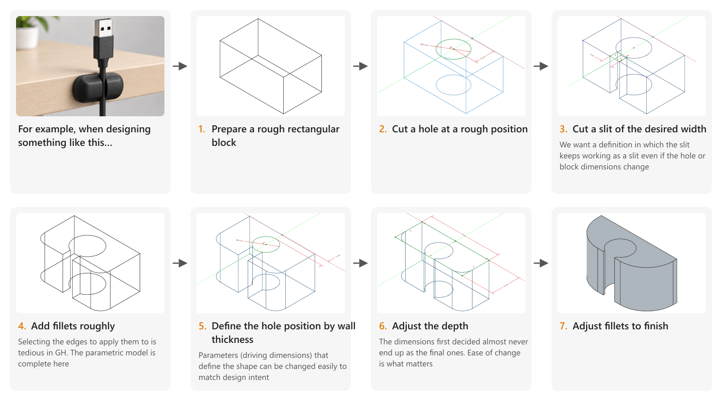
図1は、机の端にUSBケーブルを引っ掛けておく部品(USBケーブルホルダ)を設計する手順です。まず暫定的な寸法でモデリングし、最後に寸法を整えています。設計を始める前から寸法がすべて決まっていることはまずないため、後から寸法を変えても意図どおりに形が追従する定義(パラメトリックモデル)をいかに容易に作れるか、またその定義をいかに柔軟に変更できるかが重要です。図の例では、穴や直方体の寸法を変えてもスリットがスリットとして機能し続けるよう、スリットを穴のエッジ上に拘束しています(図中の手順3.)。また手順5.では、穴位置を中心で指定するよりも壁厚さで指定したくなったため、途中で寸法定義箇所を変更しています。
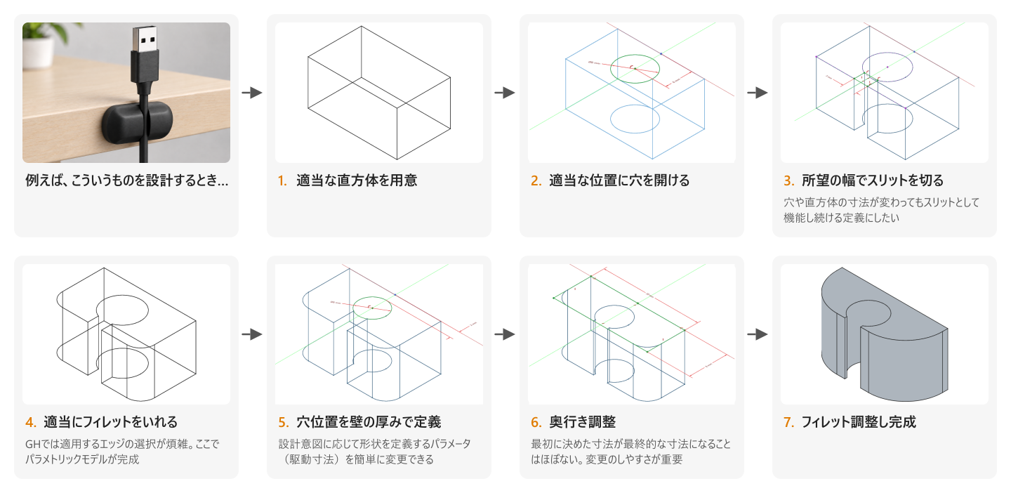
GHでも同じようなモデルは作れますが、「穴のエッジ上に頂点が来るように長方形を描く」「あるエッジにフィレットを入れる」といった操作のたびに、参照したい形状をデータフローの中でどう特定するかを考えなければなりません。また、図1の手順5.のように、形状を変えずに寸法定義箇所を変更したい場合GHではさらに煩雑です。
以上のように、手間がかかると感じていた原因は、GHに「幾何拘束」と「画面上で形状を選んで参照できるUI」がないことです。詳細設計だけ別のCADで行う手もありますが、GHのアルゴリズムによる形状定義やプラグイン資産を活かしてつくった形を、同じ環境のまま具体的なモノに仕上げたい場面は多々あります。
Grasshopperの性質と幾何拘束
GHで幾何拘束が発達しなかった理由の一つは、GHのデータ処理の考え方と、幾何拘束の考え方があまり噛み合わないためではないでしょうか。GHのデータ処理には、次のような特徴があります。
- データは上流から下流へ一方向に流れる
- コンポーネントは入力を受け取り、出力を返す
- ある処理は入力されたデータを書き換えるのではなく、新しいデータを出力する
- 同じコンポーネントに同じ入力を与えれば、同じ出力が得られる
こうした性質は、関数型プログラミングの考え方とよく似ています[1]。Grasshopperのコンポーネントとワイヤによる表現は、こうした考え方を視覚的に表現しているとも考えられます。
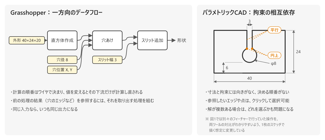
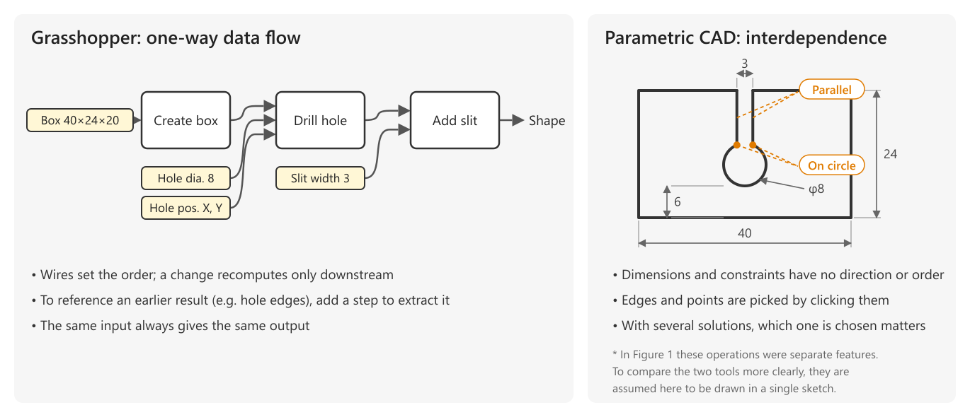
一方、パラメトリックCADで使われる幾何拘束は少し性格が異なります。前章で見たような複数の拘束条件を与え、それらを同時に満たす形状をソルバーが求めます。ここでは、単純に 入力 → 処理 → 出力 と一方向に値を計算するのではなく、複数の要素がお互いに関係し合っています。このような双方向の依存関係は、上流から下流へ値を伝播させるGrasshopperの一方向のデータフローとは、そのままではあまり相性がよくありません(図2)。
このような処理をGH上で扱う方法はないのでしょうか。一つの例が、物理演算プラグインKangaroo[2]や折紙設計プラグインCrane[3]です。これらは、複数の制約や初期状態をまとめてソルバーに入力し、その内部で反復計算を行うことで、条件を満たす形状を求めることを実現しており、GH環境の豊かさの一端を担っています。
しかしながら、KangarooやCraneを前章のUSBケーブルホルダのような部品の設計に使うのは現実的ではありません。理由は2つあります。1つはUIで、拘束をかけたい点や線を一つひとつGH上で特定する必要があり、手間がかかりすぎます。もう1つはソルバーの性質の違いです。パラメトリックCADの幾何拘束ソルバーは、すべての拘束を正確に満たす解を求めようとし、拘束同士が矛盾している場合(過拘束)は解を出さずにエラーを返します。一方、KangarooやCraneは、拘束をすべては満たせない場合でも、拘束同士の重みを考慮したほどほどの解に収束するため[4][5]、正確な寸法を求める部品設計用には向きません。これは形態探索や折紙のシミュレーションといった本来の用途に合った性質のソルバーが選ばれた結果でしょう。
パラメトリックCADという関数を作る
少し発想を変えて、GH上で幾何拘束や参照関係を定義するのではなく、パラメトリックCADそのものをGHの一つのコンポーネントにすればよいのでは? と考えました。そこで今回作ったのが、FreeCADをGHのコンポーネントとして利用できるプラグインです。Paramecium(ゾウリムシ)という名前でこちらから入手できます。
FreeCADはフリーソフトウェアのパラメトリックCADで、20年以上開発が続けられており[6]、2024年にバージョン1.0が出てから[7]かなり使い勝手が良くなってきています。今後の発展性と、無料で気軽に使える点から今回の連携相手に選定しました。
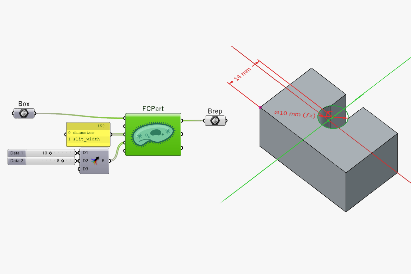
Parameciumの機能を簡単に紹介します。FreeCadPartコンポーネントをダブルクリックするとFreeCADのGUIが立ち上がり、そこで幾何拘束付きのスケッチで形状を定義する、GUIで参照をクリックしてフィレットを追加するなど、FreeCADの機能が使えます。GHから入力した形状や数値はFreeCADのツリー上で参照可能です。また、入力が変更された場合は、モデルが再計算され、結果がGHへ出力されます(動画1)。
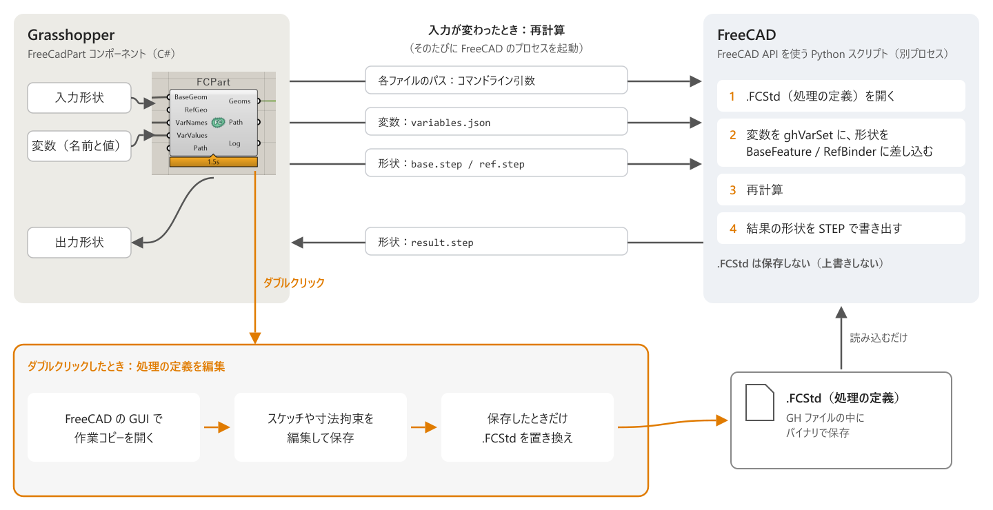
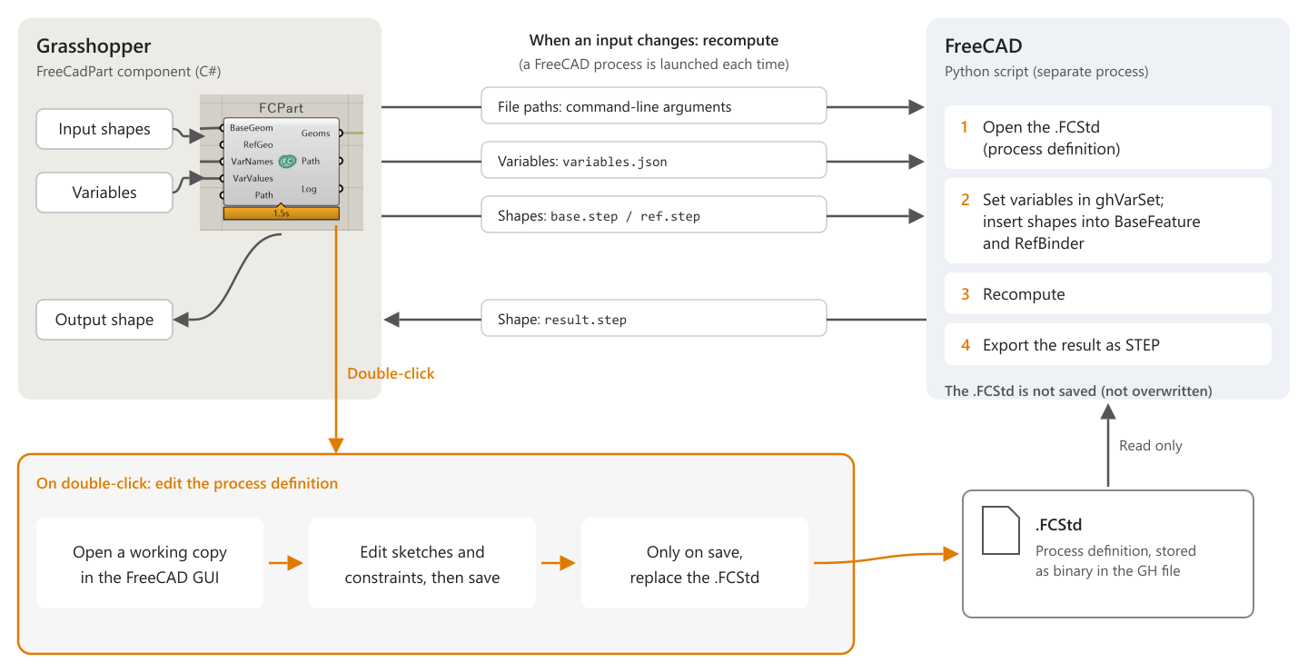
以下少々細かい話ですが、GH上での振る舞いとしてこだわった点があります。FreeCAD上で定義した処理(FCStdファイルに保存される)がGHから見ると純粋な関数として振る舞うようにすることです。ここではFCStdファイルを「関数の定義」とみなし、GHから入力される形状やパラメータに対して、同じ入力であれば同じ出力を返すようにしています。仕組みとしては、入力が変わるたびにFreeCADを別プロセスで起動し、入力形状と変数をファイルで渡して再計算した結果をGHへ戻しています(図3)
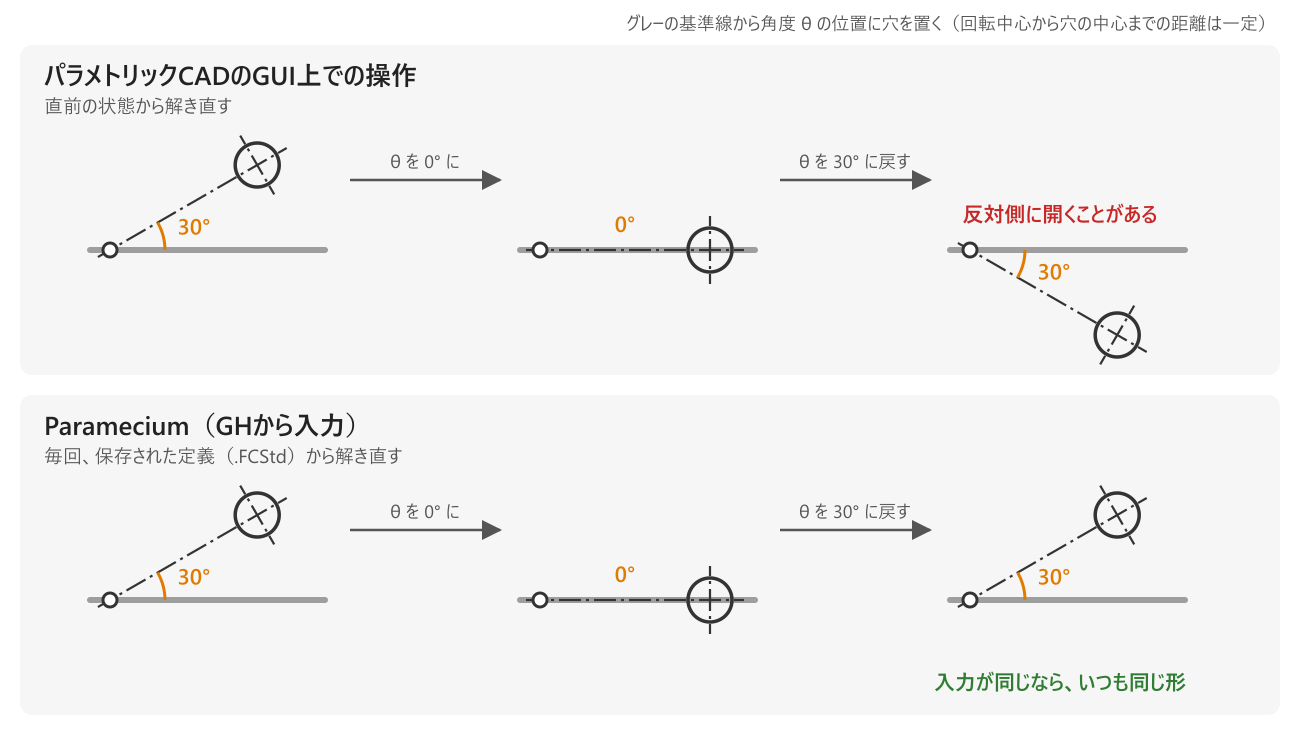
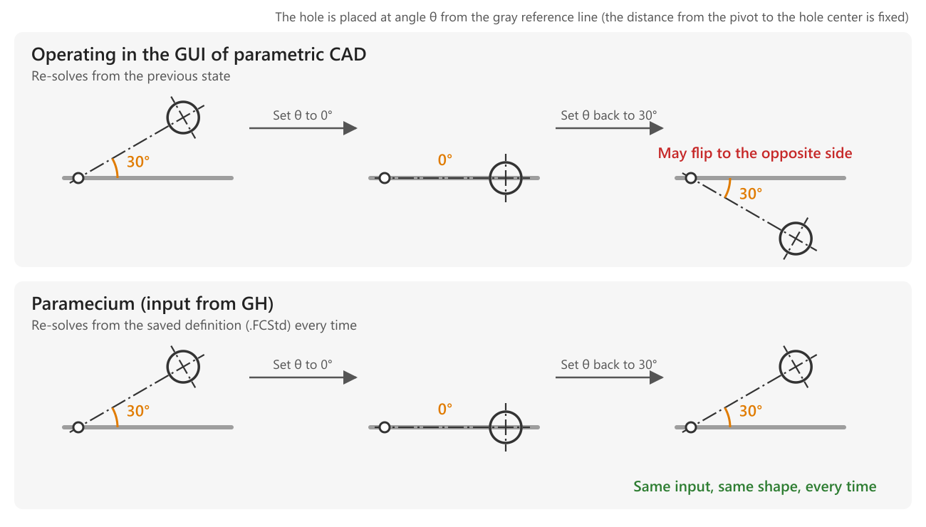
実は、通常のパラメトリックCADのUI上で寸法などのパラメータを変更する操作をする場合、上記のような純粋な関数とはならないケースがあります。例えば、スケッチ上で寸法値を変更した際、幾何拘束ソルバーでは直前の状態からソルバーにとって近い方の解に収束するため、解が複数あるような拘束を与えた場合、得られる解は直前の状態に依存します(図4上段)。
開発したプラグインでは、コンポーネントへの入力を変更しただけでは、処理の定義は変更されない(.FCStdファイルは上書きされない)仕様としており、GHから見ると純粋な関数であることを守ります(図4下段)。処理が変わるのはコンポーネントをダブルクリックして明示的に.FCStdファイルを変更した場合のみです。入力が同じなら必ず同じ形状が得られるため、GH上で最適化を行う場合も、パラメータを探索する順序によって評価結果が変わることがありません。
設計例:折紙スタンド付きスマホケース
例として、使わないときは平たく収納される折紙機構のスタンドを持つスマホケースを設計してみます。従来であれば、スマホ本体とケースのモデリングはパラメトリックCADで、折紙部分の設計はGH上のCraneで行い、ソフトを何度も行き来することになります。寸法の試行錯誤やスタンドの角度・スマホの機種変更のたびに、この行き来をやり直さなければなりません。
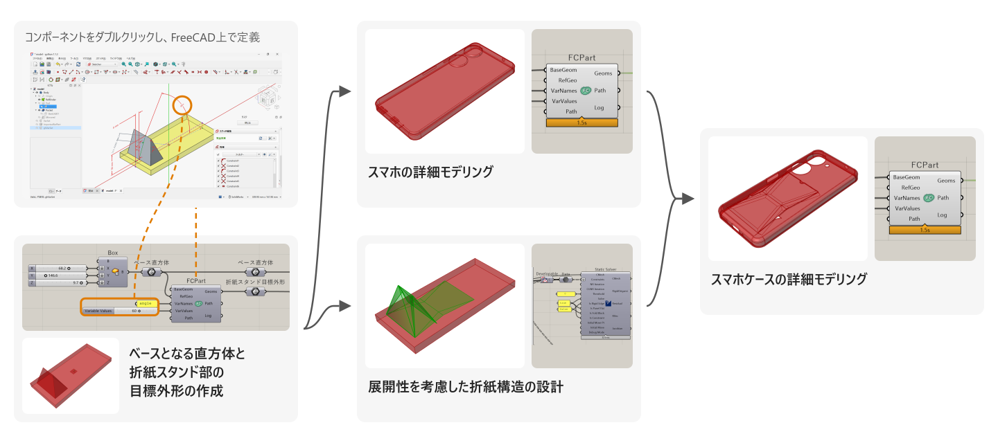
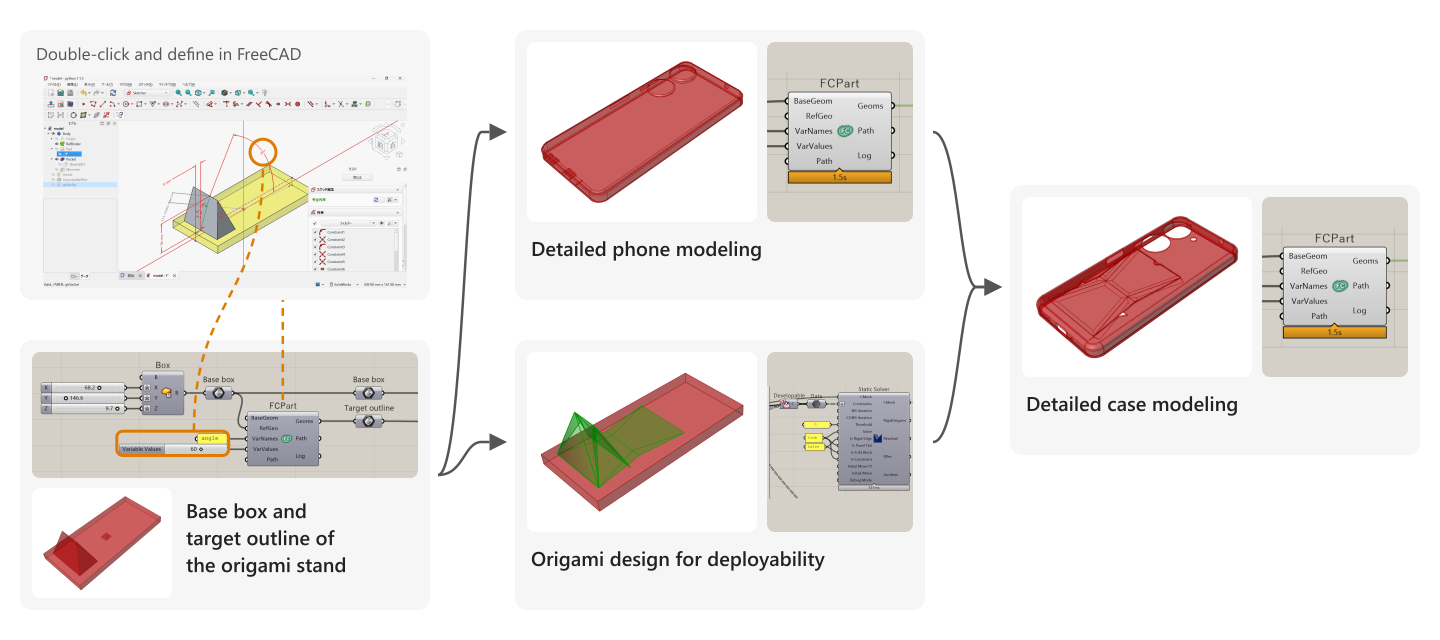
Parameciumを使った設計の流れを図5に示します。まず、ベースとなる直方体とスマホを立てる角度のパラメータをGH上で定義し、それら入力に基づいてFreeCADのGUI上でスタンドの目標外形を作ります。欲しい箇所(スマホを立てる角度)が狙いの寸法となるように形を決めるのはパラメトリックCADの得意とするところです。次に、そのスタンド目標外形に対して展開可能な折紙構造をCraneで設計し、並行してスマホ本体の細部をモデリングします。最後に、これらを入力としてケースを詳細にモデリングします。すべてがGH上でつながっているため、パラメータ変更の際も最小限の手間で済みます。
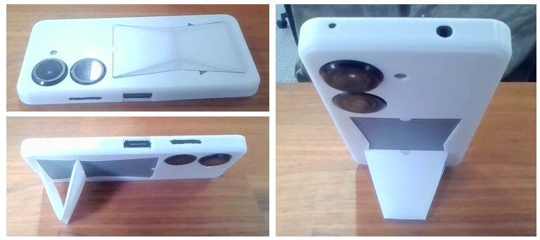
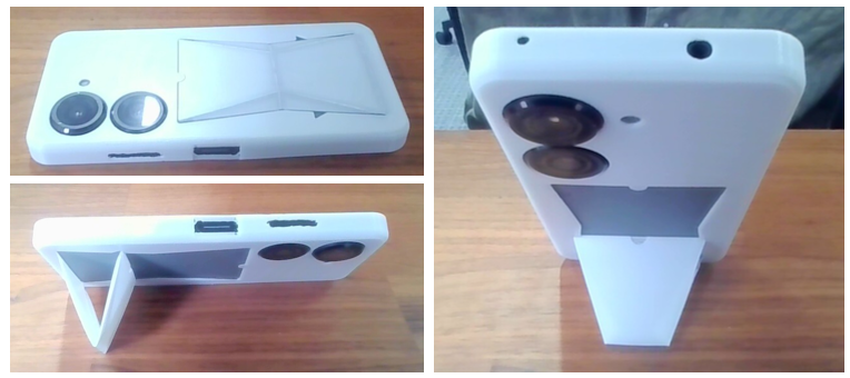
設計したスマホケースは3Dプリントし、毎日便利に使っています(図6)。
さいごに
本記事では、GrasshopperとパラメトリックCADの性質を整理し、FreeCADをGrasshopper上から利用するプラグイン「Paramecium」を紹介しました。
普段私たちは自由に設計しているようで、しばしば今目の前のツールで表現しやすい形状に囚われて設計しています。Grasshopperで設計したものはGrasshopperらしい形状、パラメトリックCADで設計したものはパラメトリックCADらしい形状になりがちです。適材適所でツールを自在に組み合わせながら良い設計をしていきたいですね。
参考文献
[1] Breaking the blanks. “Grasshopper and Functional Programming”. 2012/03/18. https://breakingtheblanks.blogspot.com/2012/03/grasshopper-and-functional-programming.html. (2026/09/27閲覧).
[2] Daniel Piker. “Kangaroo Physics”. Food4Rhino. https://www.food4rhino.com/en/app/kangaroo-physics. (2026/09/27閲覧).
[3] Kai Suto, Kotaro Tanimichi, Kanata Warisaya. “Crane”. Food4Rhino. https://www.food4rhino.com/en/app/crane. (2026/09/27閲覧).
[4] Daniel Piker. “How does Kangaroo solver work?”. Rhino Forums. 2019/11/14. https://discourse.mcneel.com/t/how-does-kangaroo-solver-work/92075. (2026/09/27閲覧).
[5] Kai Suto, Yuta Noma, Kotaro Tanimichi, Koya Narumi, Tomohiro Tachi. “Crane: An Integrated Computational Design Platform for Functional, Foldable, and Fabricable Origami Products”. ACM Transactions on Computer-Human Interaction. 30(4). 2023. https://doi.org/10.1145/3576856
[6] Wikipedia. “FreeCAD”. https://en.wikipedia.org/wiki/FreeCAD. (2026/09/27閲覧).
[7] FreeCAD News. “FreeCAD Version 1.0 Released”. 2024/11/19. https://blog.freecad.org/2024/11/19/freecad-version-1-0-released/. (2026/09/27閲覧).
Introduction
At Nature Architects, we use Rhinoceros + Grasshopper (Rhino/GH below) for many tasks, including shape generation, analysis, and optimization. Rhino is a 3D CAD application widely used in product design and architecture, and GH is a visual programming environment that runs on top of it. Combined with its rich ecosystem of plugins, it lets you generate complex shapes algorithmically.
That said, I grew up with parametric CAD for mechanical design (Creo, SolidWorks, Fusion 360, etc.) from my student days, and there have been times when designing ordinary mechanical parts in Rhino/GH felt like a lot of work (related article). But this is less a flaw of GH than the flip side of one of its strengths: a clear flow of data.
In this article, I sort out where that extra effort comes from by comparing the nature of GH and parametric CAD. As a solution, I then introduce "Paramecium", a GH plugin that treats FreeCAD, one of the parametric CADs, as a "function". Finally, I show a design example: a smartphone case with an origami stand.
Part Design in Parametric CAD
In parametric CAD for mechanical design such as Creo, SolidWorks, and Fusion 360, you give a sketch conditions (geometric constraints) like "this line is parallel to that line", "this point lies on this circle", or "this dimension is 10 mm", and the shape is determined so as to satisfy them (related article). To specify what a constraint applies to, or where to add a feature such as a fillet, you click edges and faces on the screen to reference them.
Figure 1 shows the steps for designing a part that hooks a USB cable onto the edge of a desk (a USB cable holder). I first model it with provisional dimensions and finalize the dimensions at the end. Since it is rare for every dimension to be settled before design begins, what matters is how easily you can build a definition (a parametric model) whose shape follows as intended when dimensions change later, and how flexibly you can modify that definition afterward. In this example, the slit is constrained to the edge of the hole so that it keeps working as a slit even if the dimensions of the hole or the rectangular block change (step 3 in the figure). In step 5, I found it more natural to specify the hole position by the wall thickness than by its center, so I changed where the dimension is defined partway through.
You can build a similar model in GH, but every operation, such as "draw a rectangle whose vertex lies on the edge of the hole" or "add a fillet to a particular edge", requires you to work out how to identify the geometry you want to reference within the data flow. And when you want to move where a dimension is defined without changing the shape, as in step 5 of Figure 1, it becomes even more cumbersome in GH.
So the reason it felt like so much work is that GH has neither "geometric constraints" nor a "UI for selecting and referencing shapes on the screen". You could do only the detailed design in another CAD, but there are many situations where you want to finish a form created with GH's algorithmic shape definitions and plugin ecosystem into a concrete object in the same environment.
The Nature of Grasshopper and Geometric Constraints
One reason geometric constraints did not develop in GH may be that GH's way of processing data does not fit well with the idea behind geometric constraints. GH's data processing has the following characteristics:
- Data flows in one direction, from upstream to downstream
- A component receives inputs and returns outputs
- A process does not rewrite its input data but outputs new data
- Giving the same inputs to the same component always yields the same outputs
These properties closely resemble the ideas of functional programming [1]. The components and wires of Grasshopper can be seen as a visual expression of those ideas.
Geometric constraints in parametric CAD, on the other hand, are somewhat different in character. You give multiple constraint conditions like those in the previous section, and a solver finds a shape that satisfies them all at once. Here, values are not simply computed in one direction as input → process → output; multiple elements are related to one another. Such bidirectional dependencies do not fit well, as they are, with Grasshopper's one-way data flow that propagates values from upstream to downstream (Figure 2).
Is there no way to handle this kind of processing in GH? One example is the physics plugin Kangaroo [2] and the origami design plugin Crane [3]. They take multiple constraints and an initial state together as input to a solver, and find a shape that satisfies the conditions through iterative computation inside it. They are part of what makes the GH environment so rich.
However, it is not realistic to use Kangaroo or Crane to design a part like the USB cable holder in the previous section, for two reasons. The first is the UI: you would have to identify each point or line you want to constrain within GH, which takes far too much effort. The second is the difference in solver behavior. The geometric constraint solver of parametric CAD tries to find a solution that satisfies every constraint exactly, and when the constraints contradict each other (over-constrained), it returns an error instead of a solution. Kangaroo and Crane, on the other hand, converge to a reasonable solution that takes the weights of the constraints into account even when not all of them can be satisfied [4][5], so they are not suited to part design that requires exact dimensions. This is probably the result of choosing solvers whose properties match their intended uses, such as form finding and origami simulation.
Building Parametric CAD as a Function
Changing my approach a little, I thought: instead of defining geometric constraints and reference relationships in GH, why not make parametric CAD itself a component of GH? The result is a plugin that lets you use FreeCAD as a GH component. It is called Paramecium, and it is available here.
FreeCAD is free parametric CAD software that has been under development for more than 20 years [6], and it has become considerably easier to use since version 1.0 was released in 2024 [7]. I chose it as the partner for this integration because of its potential for future development and because it is free and easy to try.
Here is a quick tour of Paramecium's features. When you double-click the FreeCadPart component, the FreeCAD GUI launches, and you can use FreeCAD's features there: define a shape with a sketch that has geometric constraints, add a fillet by clicking references in the GUI, and so on. Shapes and numbers input from GH can be referenced in FreeCAD's tree. When an input changes, the model is recomputed and the result is output to GH (Video 1).
Here is a slightly more detailed point, but there is something I was particular about regarding behavior on the GH side: the process defined in FreeCAD (saved in a *.FCStd file) should behave as a pure function from GH's point of view. Here the FCStd file is regarded as the "definition of a function", and for the same input shapes and parameters coming from GH, it returns the same output. In terms of mechanism, every time an input changes, FreeCAD is launched as a separate process, the input shapes and variables are passed via files, and the recomputed result is returned to GH (Figure 3).
In fact, when you change a parameter such as a dimension in the UI of ordinary parametric CAD, it does not always behave as a pure function like the one above. For example, when you change a dimension value in a sketch, the geometric constraint solver converges to whichever solution is closest to the previous state. So if the constraints admit multiple solutions, the solution you get depends on the previous state (Figure 4, top).
With the plugin I developed, changing an input to the component does not change the process definition (the *.FCStd file is not overwritten), so it remains a pure function from GH's point of view (Figure 4, bottom). The process changes only when you double-click the component and explicitly modify the *.FCStd file. Because the same input always yields the same shape, even when optimizing in GH, the evaluation results do not change depending on the order in which parameters are explored.
Design Example: A Smartphone Case with an Origami Stand
As an example, let's design a smartphone case with an origami-mechanism stand that folds flat when not in use. Conventionally, you would model the phone and the case in parametric CAD and design the origami part with Crane in GH, going back and forth between the software many times. Every time you iterate on dimensions, or change the stand angle or the phone model, you would have to redo this back-and-forth.
Figure 5 shows the design flow using Paramecium. First, I define parameters in GH for the base rectangular block and the angle at which the phone stands, and based on these inputs I create the target outline of the stand in the FreeCAD GUI. Shaping it so that the place that matters (the angle at which the phone stands) comes out at the intended dimension is what parametric CAD does best. Next, I design a deployable origami structure for that target outline with Crane, and in parallel model the details of the phone itself. Finally, I use these as inputs to model the case in detail. Since everything is connected within GH, changing a parameter takes minimal effort.
I 3D-printed the designed case, and I use it conveniently every day (Figure 6).
Conclusion
In this article, I sorted out the nature of Grasshopper and parametric CAD, and introduced "Paramecium", a plugin that lets you use FreeCAD from within Grasshopper.
We like to think we design freely, but we are often constrained by shapes that are easy to express in the tool in front of us. What is designed in Grasshopper tends to look like Grasshopper, and what is designed in parametric CAD tends to look like parametric CAD. I hope to keep combining tools freely, using the right one for each job, to make good designs.
References
[1] Breaking the blanks. "Grasshopper and Functional Programming". 2012/03/18. https://breakingtheblanks.blogspot.com/2012/03/grasshopper-and-functional-programming.html. (Accessed 2026/09/27).
[2] Daniel Piker. "Kangaroo Physics". Food4Rhino. https://www.food4rhino.com/en/app/kangaroo-physics. (Accessed 2026/09/27).
[3] Kai Suto, Kotaro Tanimichi, Kanata Warisaya. "Crane". Food4Rhino. https://www.food4rhino.com/en/app/crane. (Accessed 2026/09/27).
[4] Daniel Piker. "How does Kangaroo solver work?". Rhino Forums. 2019/11/14. https://discourse.mcneel.com/t/how-does-kangaroo-solver-work/92075. (Accessed 2026/09/27).
[5] Kai Suto, Yuta Noma, Kotaro Tanimichi, Koya Narumi, Tomohiro Tachi. "Crane: An Integrated Computational Design Platform for Functional, Foldable, and Fabricable Origami Products". ACM Transactions on Computer-Human Interaction. 30(4). 2023. https://doi.org/10.1145/3576856
[6] Wikipedia. "FreeCAD". https://en.wikipedia.org/wiki/FreeCAD. (Accessed 2026/09/27).
[7] FreeCAD News. "FreeCAD Version 1.0 Released". 2024/11/19. https://blog.freecad.org/2024/11/19/freecad-version-1-0-released/. (Accessed 2026/09/27).
